
Unit installation


Remote HWG
Revised: 3 May, 2010
6
Water-Source Heating and Cooling Systems
Hot Water Generator Module Installation
Outdoor Compressor Section Only
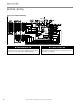
Figure 3a: Outdoor Compressor Section HWG Installation
Figure 4: HWG Refrigerant Line Sizing
Capacity
Line Set Size
1/2” OD 5/8” OD 3/4” OD
2 Ton
Up to 16 ft.
[4.9m]
Up to 30 ft.
[9.1m]
N/A
3 Ton
Up to 9 ft.
[2.7m]
Up to 25 ft.
[7.6m]
Up to 30 ft.
[9.1m]
4 Ton
Up to 5 ft.
[1.5m]
Up to 13 ft.
[4.0m]
Up to 30 ft.
[9.1m]
5 Ton N/A
Up to 9 ft.
[2.7m]
Up to 25 ft.
[7.6m]
As a guideline add 1.0 oz. of refrigerant for the heat ex-
changer plus 1.0 oz. for each 10 ft of 1/2” OD refrigerant
line, if the weighed charge method is used (28g for the heat
exchanger plus 9g per meter of 1/2” OD refrigerant line).
Figure 3b: Remote HWG Module
Figure 3c: HWG Service Valves
Figure 3d: HWG Bypass Valve
Valve Open
(HWG Bypassed)
Valve Closed
(HWG Activated)
Control
Board
Circulator
HWG
Water Out
HWG
Refr Out
HWG
Refr In
High Voltage
HWG
Water In
16.2”
11.1”
7.1”
Low
Voltage
HWG
Water In
Fully Insulated
Lines to the HWG
Refr to
HWG
Refr from
HWG
HWG
Line Valves
HWG
Bypass
Valve
Refr
to HWG
Refr from
HWG