HS/HL/HP and VS/VL/VP Series Horizontal & Vertical Series Water Source Heat Pumps Installation, Operation, & Maintenance Instructions
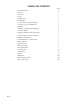
TABLE OF CONTENTS Page Page 2 General Information 3 Inspection 3 Introduction 3 Storage 3 Unit Protection 3 Pre-Installation 3 Location and Access-Horizontal Units 4 Location and Access-Vertical Units 5 Installation 6 Installation of Supply and Return Piping 6 Condensate Piping 6 Hanging and Mounting a Horizontal Unit 7 Sound Attenuation for Horizontal Units 8 Installing a Vertical Unit 8 Sound Attenuation for Vertical Units 8 Electrical Wiring 8 Operating Limits 9 Starti
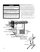
GENERAL INFORMATION Inspection Unit Protection Upon receipt of shipment at the job site, carefully check the shipment against the bill of lading. Make sure all units have been received. Verify Hanger Brackets are located inside the fan compartment of Horizontal Units. Inspect the carton or crating of each unit, and inspect each unit for damage. Assure that the carrier makes proper notation of any shortages or damage on all copies of the freight bill and he/she completes a Carrier Inspection Report.
Horizontal Units Location and Access To avoid the release of refrigerant into the atmosphere, the refrigerant circuit of this unit MUST only be serviced by technicians who meet local, state and federal proficiency requirements. All refrigerant discharged from this unit must be recovered without exception. Technicians MUST follow industry accepted guidelines and all local, state and federal statutes for the recovery and disposal of refrigerants.
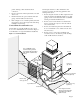
panels, discharge collars and all electrical connections. 3. Provide a duct slot for filter replacement, if a return duct is used. 4. DO NOT obstruct the space beneath the unit with piping, electrical cables and other items. 5. Refer to Figure 2. Use a manual portable jack to lift the unit and to support the weight of the unit during installation and servicing. Vertical Units Location and Access Vertical Units are typically installed in a floor level closet or in a small mechanical room.
INSTALLATION The installation of Horizontal and Vertical Water Source Heat Pump units and all associated components, parts and accessories which make up the installation shall be in accordance with the regulations of ALL authorities having jurisdiction and MUST conform to all applicable Codes. It is the responsibility of the Installing Contractor to determine and comply with ALL applicable Codes and Regulations. Maximum allowable torque for brass fittings is 30 footpounds.
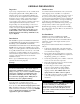
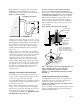
Figure 5 illustrates a typical trap and vent used with HS/HL/HP & VS/VL/VP Heat Pumps. Design the length of the trap (water-seal) based upon the amount of Figure 5. Condensate Drain To avoid condensate overflow in Horizontal Units: Horizontal Units sizes 006-030 must be hung level to ensure proper condensate drainage. Horizontal Units sizes 036-120 must be hung pitched 1/4" to 1/2" toward the condensate drain connection to ensure proper drainage.
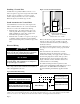
Figure 7. Vertical Sound Attenuation Installing a Vertical Unit Vertical units are typically installed on the floor or on shelves designed to support the weight of the unit. Install the unit on a piece of rubber or neoprene for sound isolation. The pad should be 1/2" to 3/8" in thickness. Extend the pad beyond all four edges of unit. Sound Attenuation for Vertical Units Sound minimization is achieved by enclosing the unit within a small mechanical room or a closet.
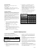
Operating Limits 4. Determination of operating limits is dependent primarily upon three factors: 1) return air temperature, 2) water temperature and 3) ambient temperature. When any one of these factors is at minimum or maximum levels, the other two factors should be at normal levels to ensure proper unit operation (refer to Table 2). 5. Extreme variations in temperature and humidity and corrosive water or air will adversely affect unit performance, reliability and service life.
7. Refill the system and add trisodium phosphate in a proportion of approximately one pound per 150 gallons of water. Reset the boiler to raise the loop temperature to about 100°F. Horizontal and Vertical units. Refill the system and bleed off all air. 9. ! CAUTION ▲ To avoid possible damage to piping systems constructed of plastic piping, DO NOT allow loop temperature to exceed 110°F. Circulate the solution for a minimum of eight to 24 hours.
UNIT START-UP Use the procedure below to initiate proper unit start-up: WARNING a. When the disconnect switch is closed, high voltage is present in some areas of the electrical panel. Exercise caution when working with energized equipment. 1. Adjust all valves to their full open position. Turn on the line power to all heat pump units. 2. Operate each unit in the cooling cycle. Room temperature should be approximately 70° to 75°F DB, and 61° to 65°F WB.
Page 12
CLIMATE MASTER, INC. LIMITED EXPRESS WARRANTY/ LIMITATION OF REMEDIES AND LIABILITY It is expressly understood that unless a statement is specifically identified as a warranty, statements made by Climate Master, Inc.
Page 14
Page 15
MAINTENANCE Maintenance Procedures Perform the maintenance procedures outlined below periodically, as indicated. WARNING To prevent injury or death due to electrical shock or contact with moving parts, open unit disconnect switch before servicing unit. Unit Inspection: Visually inspect the unit annually. Pay special attention to hose assemblies. Repair any leaks and replace deteriorated hoses immediately. Compressor: Conduct an amperage check on the compressor annually.