
Specifications


ClimateMaster works continually to improve its products. As a result, the design and specifi cations of each product at the time of order may be changed without notice and may not be as described herein. Please contact ClimateMaster's Customer
Service Department at 1-405-745-6000 for specifi c information on the current design and specifi cations. Statements and other information contained herein are not express warranties and do not form the basis of any bargain between the parties,
but are merely ClimateMaster's opinion or commendation of its products. The latest version of this document is available at climatemaster.com.
Page ______ of ______Rev.: 29 May, 2009BLC105 - 53
VHS Series 60Hz - R22 Submittal Data Eng/I-P
Geothermal Heat Pump Systems
Option: High static motors.
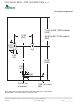
Chassis:
The chassis, which incorporates the air coil, water coil, drain pan, and compressor, shall be easily installed for quick jobsite
installation and future servicing purposes. The slide in chassis shall have an insulated panel separating the fan compartment from
the compressor compartment. Compressors are not in the air stream. The chassis base shall be fabricated from heavy gauge
galvanized steel formed to match the slide in rails of the cabinet. All electrical connections between the chassis and cabinet shall
be made via locking quick-connects. Units shall have a factory installed 1 inch (25.4mm) thick fi lter bracket and throwaway type
glass fi ber fi lter. Furnish one spare set of fi lters.
Water connections between chassis and the cabinet shall be accomplished via a hose kit consisting of Kevlar-reinforced EPDM
core hose surrounded by a stainless-steel braid. Hose kit shall have brass fi ttings with stainless-steel ferrules. Hose ends shall be
solid External NPT which connects to mating fi tting on cabinet shut off ball valve(s), and Internal NPSM (National Pipe Straight
Mechanical) swivel end with fi ber or EPDM washer which connects to mating threaded end connection on chassis. The hose kit
shall be rated for 350 psi (2412 kPa) design working pressure.
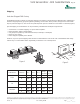
Refrigerant Circuit:
Units shall have a sealed refrigerant circuit including a hermetic compressor, thermostatic expansion valve for refrigerant metering,
an enhanced corrugated aluminum lanced fi n and rifl ed copper tube refrigerant to air heat exchanger, a coaxial (tube in tube)
refrigerant to water heat exchanger, and safety controls including a high pressure switch, low pressure switch (loss of charge),
a high level condensate sensor, water coil low temperature sensor, and air coil low temperature sensor. Access fi ttings shall be
factory installed on high and low pressure refrigerant lines to facilitate fi eld service. Activation of any safety device shall prevent
compressor operation via a microprocessor lockout circuit. The lockout shall be reset at the thermostat or disconnect switch. Units
that cannot be reset at the thermostat shall not be acceptable.
Hermetic compressors shall be internally sprung and externally isolated (with computer selected spring isolation). Compressor
shall have thermal overload protection. Compressor shall be located in an insulated compartment away from air stream to
minimize sound transmission. All units (except units with rotary compressors) shall include a discharge muffl er to further enhance
sound attenuation.
Refrigerant to air heat exchangers shall utilize enhanced corrugated lanced aluminum fi ns and rifl ed copper tube construction
rated to withstand 450 PSIG (3101 kPa) refrigerant working pressure. Refrigerant to water heat exchangers shall be of copper
inner water tube and steel refrigerant outer tube design, rated to withstand 450 PSIG (3101 kPa) working refrigerant pressure and
450 PSIG (3101 kPa) working water pressure. The refrigerant to water heat exchanger shall be “electro-coated” with a low cure
cathodic epoxy material a minimum of 0.4 mils thick (0.4 – 1.5 mils range) on all surfaces. The black colored coating shall provide
a minimum of 1000 hours salt spray protection per ASTM B117-97 on all external steel and copper tubing. The material shall be
formulated without the inclusion of any heavy metals and shall exhibit a pencil hardness of 2H (ASTM D3363-92A), crosshatch
adhesion of 4B-5B (ASTM D3359-95), and impact resistance of 160 in-lbs (184 kg-cm) direct (ASTM D2794-93).
Refrigerant metering shall be accomplished by thermostatic expansion valve only. Expansion valves shall be dual port balanced
types with external equalizer for optimum refrigerant metering. Reversing valve shall be four-way solenoid activated refrigerant
valve, which shall default to heating mode should the solenoid fail to function. If the reversing valve solenoid defaults to cooling
mode, an additional low temperature thermostat must be provided to prevent over-cooling an already cold room.
Option: The refrigerant to air heat exchanger shall be “electro-coated” with a low cure cathodic epoxy material a minimum of
0.4 mils thick (0.4 – 1.5 mils range) on all surfaces. The black colored coating shall provide a minimum of 1000 hours salt
spray protection per ASTM B117-97 on all galvanized end plates and copper tubing, and a minimum of 2000 hours of salt
spray on all aluminum fi ns. The material shall be formulated without the inclusion of any heavy metals and shall exhibit a
pencil hardness of 2H (ASTM D3363-92A), crosshatch adhesion of 4B-5B (ASTM D3359-95), and impact resistance of 160
in-lbs (184 kg-cm) direct (ASTM D2794-93).
Option: The unit will be supplied with cupro nickel coaxial water to refrigerant heat exchanger.
Option: The unit will be supplied with internally factory mounted two-way water valve for variable speed pumping requirements.
A factory-mounted or fi eld-installed high pressure switch shall be installed in the water piping to disable compressor
operation in the event water pressures build due to water freezing in the piping system.
Vertical High Rise - VHS Series
Engineering Specifi cations Rev.: 05/29/09 Page 2