Genesis Large (GL) Series Commercial Horizontal & Vertical Packaged Heat Pump Revision: 13 April, 2009B GENESIS LARGE (GL) SERIES Table of Contents Model Nomenclature 3 Electrical - Low Voltage 26 Physical Data 4 Dimensional Data 5 CXM/DXM LonWorks or MPC Control Operation 28 General Information 13 Wiring Schematic 29 Horizontal Unit Installation 14 ClimaDry Reheat Sequence of Operation 38 Vertical Unit Installation 16 Blower Adjustment 41 Duct System Design & Installation Guidelines
THE SMART SOLUTION FOR ENERGY EFFICIENCY Genesis Large (GL) Series R e v.
C L I M AT E M A S T E R W AT E R - S O U R C E H E AT P U M P S Genesis Large (GL) Series R e v. : 1 3 A p r i l , 2 0 0 9 B GLH Physical Data Model 072 096 120 Refrigerant Circuit Compressor (2 each) Factory Charge oz [kg] per Circuit Recip Scroll Scroll 56 [1.59] 50 [1.417] 80 [2.268] 1.5 [1.1] 2 [1.5] 2 [1.5] 2 [1.5] 3 [2.2] 3 [2.2] Fan Motor Standard (hp) [kW] Large (hp) [kW] Blower 12 x 11 [30.5 x 27.9] Wheel Size -Dia x W (in) [cm] 2 - 10 x 10 [25.4 x 25.4] 2 - 11 x 10 [27.
THE SMART SOLUTION FOR ENERGY EFFICIENCY Genesis Large (GL) Series R e v. : 1 3 A p r i l , 2 0 0 9 B GLH072 Dimensional Data 1-1/8” [2.8cm] Hole 1/2” [1.2cm] Hole B 07/28/08B Model 072 in. cm. Overall Cabinet Discharge Connections Duct Flange (± 0.10in, ±2.5mm) A B C D Width Depth Height Supply Height 36.3 92.2 72.3 183.6 21.6 54.9 16.0 40.6 E F G H Water Connections K L M Electrical Knockouts / Holes N O P Q R Supply Depth 14.5 36.8 3.5 8.9 1.0 2.5 16.0 40.6 21.0 53.
C L I M AT E M A S T E R W AT E R - S O U R C E H E AT P U M P S Genesis Large (GL) Series R e v. : 1 3 A p r i l , 2 0 0 9 B GLH096-120 Dimensional Data 1-1/8” [2.8cm] Hole 1/2” [1.2cm] Hole B 08/22/08B Model Overall Cabinet Discharge Connections Duct Flange (± 0.10in, ±2.5mm) A B C D Width Depth Height Supply Height E F G H Water Connections K L M Electrical Knockouts / Holes N O P Q Supply Depth S T Return Depth Return Height U V 096 in. cm. 36.3 92.2 72.3 183.6 21.
THE SMART SOLUTION FOR ENERGY EFFICIENCY Genesis Large (GL) Series R e v. : 1 3 A p r i l , 2 0 0 9 B GLV080-120 Dimensional Data Back Return Front Supply (BF) Front Return Back Supply (FB) A B D E W 3' [91cm] Service Access Return Air C BSP BSP Air Out V Air Out 1 [2.54cm] F S 1 [2.54cm] T Return Air CSP R CAP NRP CSP CAP U P O 0.75 [1.
C L I M AT E M A S T E R W AT E R - S O U R C E H E AT P U M P S Genesis Large (GL) Series R e v. : 1 3 A p r i l , 2 0 0 9 B GLV080-120 Dimensional Data with ClimaDry Reheat Back Return Front Supply (BF) Notes: 1. SERVICE ACCESS Provided on unit Front and Back sides only. No service access from unit side panels. 2. While clear access to all removable panels is not required, it may be. Access to some panels will always be required.
THE SMART SOLUTION FOR ENERGY EFFICIENCY Genesis Large (GL) Series R e v. : 1 3 A p r i l , 2 0 0 9 B GLV160-240 Dimensional Data E Air Out B D F D G A Air Out 1 [2.5cm] 1.75 [4.45cm] Air Out Air Out BSP BSP W Return Air BSP R C Back Side Return Air 6.3 [15.9cm] S V Return Air S T P CAP CSP U CAP Q CSP 4 5 0.75 [1.
C L I M AT E M A S T E R W AT E R - S O U R C E H E AT P U M P S Genesis Large (GL) Series R e v. : 1 3 A p r i l , 2 0 0 9 B GLV160-240 Dimensional Data with ClimaDry Reheat E Air Out B D F D G A Air Out 1 [2.5cm] 1.75 [4.45cm] Air Out Air Out BSP BSP W Return Air BSP R C Back Side Return Air 6.3 [15.9cm] S V Return Air S T P CAP CSP U CAP Q CSP 4 5 0.75 [1.
THE SMART SOLUTION FOR ENERGY EFFICIENCY Genesis Large (GL) Series R e v. : 1 3 A p r i l , 2 0 0 9 B GLV300 Dimensional Data Air Out B D G D F Notes: 1. Front & Side access is preferred for service access. However, all components may be serviced from the front access panel if side access is not available. 2. While clear access to all removable panels is not required, installer should take care to comply with all building codes and allow adequate clearance for future field service.
C L I M AT E M A S T E R W AT E R - S O U R C E H E AT P U M P S Genesis Large (GL) Series R e v. : 1 3 A p r i l , 2 0 0 9 B GLV300 Dimensional Data with ClimaDry Reheat Notes: 1. Front & Side access is preferred for service access. However, all components may be serviced from the front access panel if side access is not available. 2.
THE SMART SOLUTION FOR ENERGY EFFICIENCY Genesis Large (GL) Series R e v. : 1 3 A p r i l , 2 0 0 9 B General Information Inspection Upon receipt of the equipment, carefully check the shipment against the bill of lading. Make sure all units have been received. Inspect the carton or crating of each unit, and inspect each unit for damage. Assure the carrier makes proper notation of any shortages or damage on all copies of the freight bill and completes a common carrier inspection report.
C L I M AT E M A S T E R W AT E R - S O U R C E H E AT P U M P S Genesis Large (GL) Series R e v. : 1 3 A p r i l , 2 0 0 9 B Installation GL Horizontal Unit Location GL units are NOT designed for outdoor installation. Locate the unit in an INDOOR area that allows enough space for installation and for service personnel to perform typical maintenance or repairs without removing from the ceiling. Horizontal units are typically installed above a false ceiling or in a ceiling plenum.
THE SMART SOLUTION FOR ENERGY EFFICIENCY Genesis Large (GL) Series R e v.
C L I M AT E M A S T E R W AT E R - S O U R C E H E AT P U M P S Genesis Large (GL) Series R e v. : 1 3 A p r i l , 2 0 0 9 B Installation Figure 2b: Typical Vertical Installation 16 Vertical Location and Access GL units are NOT designed for outdoor installation. Locate the unit in an indoor area that allows enough space for installation and for service personnel to perform typical maintenance or repairs. GLV units are typically installed in a floor level closet or in a small mechanical room.
THE SMART SOLUTION FOR ENERGY EFFICIENCY Genesis Large (GL) Series R e v. : 1 3 A p r i l , 2 0 0 9 B Installation • • • • Include at least one 90-degree turn in supply air ducts to reduce noise transmission. Existing ducts must be checked to insure proper size and configuration prior to installation of any replacement unit. Also inspect for and repair all air leaks in existing ducts. Units may only be connected to a dedicated duct system.
C L I M AT E M A S T E R W AT E R - S O U R C E H E AT P U M P S Genesis Large (GL) Series R e v. : 1 3 A p r i l , 2 0 0 9 B Piping Installation Installation of Supply and Return Piping Follow these piping guidelines. 1. Install a drain valve at the base of each supply and return riser to facilitate system flushing. 2. Install shut-off / balancing valves and unions at each unit to permit unit removal for servicing. 3. Place strainers at the inlet of each system circulating pump. 4.
THE SMART SOLUTION FOR ENERGY EFFICIENCY Genesis Large (GL) Series R e v. : 1 3 A p r i l , 2 0 0 9 B Condensate Installation Condensate Piping Units are typically installed directly above each other on successive floors with condensate drains located near the units. Pitch the unit toward the drain as shown in Figure 4a to improve the condensate drainage. Ensure that unit pitch does not cause condensate leaks inside the cabinet.
C L I M AT E M A S T E R W AT E R - S O U R C E H E AT P U M P S Genesis Large (GL) Series R e v. : 1 3 A p r i l , 2 0 0 9 B Water-Loop Heat Pump Applications Commercial systems typically include a number of units plumbed to a common piping system. Any unit plumbing maintenance work can introduce air into the piping system, therefore air elimination equipment is a major portion of the mechanical room plumbing.
THE SMART SOLUTION FOR ENERGY EFFICIENCY Genesis Large (GL) Series R e v. : 1 3 A p r i l , 2 0 0 9 B Ground-Loop Heat Pump Applications CAUTION! CAUTION! The following instructions represent industry accepted installation practices for Closed Loop Earth Coupled Heat Pump Systems. They are provided to assist the contractor in installing trouble free ground loops. These instructions are recommended only. State and Local Codes MUST be followed and installation MUST conform to ALL applicable Codes.
C L I M AT E M A S T E R W AT E R - S O U R C E H E AT P U M P S Genesis Large (GL) Series R e v. : 1 3 A p r i l , 2 0 0 9 B Ground-Loop Heat Pump Applications Antifreeze In areas where minimum entering loop temperatures drop below 40°F (5°C) or where piping will be routed through areas subject to freezing, anti-freeze is needed. Alcohols and glycols are commonly used as antifreezes, however your local sales manager should be consulted for the antifreeze best suited to your area.
THE SMART SOLUTION FOR ENERGY EFFICIENCY Genesis Large (GL) Series R e v. : 1 3 A p r i l , 2 0 0 9 B Ground-Water Heat Pump Applications devices are typically an orifice of plastic material that are designed to allow a specified flow rate. These are mounted on the outlet of the water control valve. On occasion, these valves can produce a velocity noise that can be reduced by applying some back pressure. This is accomplished by slightly closing the leaving isolation valve of the well water setup.
C L I M AT E M A S T E R W AT E R - S O U R C E H E AT P U M P S Genesis Large (GL) Series R e v. : 1 3 A p r i l , 2 0 0 9 B Electrical Data WARNING! CAUTION! Use only copper conductors for field installed electrical wiring. Unit terminals are not designed to accept other types of conductors. To avoid possible injury or death due to electrical shock, open the power supply disconnect switch and secure it in an open position during installation.
THE SMART SOLUTION FOR ENERGY EFFICIENCY Genesis Large (GL) Series R e v. : 1 3 A p r i l , 2 0 0 9 B Table 4B: GLV Electrical Data All GLV Units Standard GLV Unit Compressor Fan Motor FLA Min Circuit Amp Model Voltage Code Voltage Min/ Max Voltage Blower Option GLV080 H 208-230/60/3 197/253 A, B, C 1 20.7 156 5.0 25.7 30.9 50 1.1 26.8 32.0 50 GLV080 H 208-230/60/3 197/253 E 1 20.7 156 6.2 26.9 32.1 50 1.1 28.0 33.2 50 GLV080 F 460/60/3 414/506 A, B, C 1 10.
C L I M AT E M A S T E R W AT E R - S O U R C E H E AT P U M P S Genesis Large (GL) Series R e v. : 1 3 A p r i l , 2 0 0 9 B Electrical - Power Wiring WARNING! WARNING! To avoid possible injury or death due to electrical shock, open the power supply disconnect switch and secure it in an open position during installation. CAUTION! CAUTION! Use only copper conductors for field installed electrical wiring. Unit terminals are not designed to accept other types of conductors.
THE SMART SOLUTION FOR ENERGY EFFICIENCY Genesis Large (GL) Series R e v. : 1 3 A p r i l , 2 0 0 9 B Electrical - Low Voltage 2-The valve will draw approximately 25-35 VA through the “Y” signal of the thermostat. Note: This can overheat the anticipators of electromechanical thermostats. Therefore only relay or triac based thermostats should be used.
C L I M AT E M A S T E R W AT E R - S O U R C E H E AT P U M P S Genesis Large (GL) Series R e v. : 1 3 A p r i l , 2 0 0 9 B CXM/DXM, LonWorks or MPC Control Operation Note: See CXM AOM (part # 97B0003N12) or DXM AOM (97B0003N13) or Lon Controller AOM (97B0013N01) and MPC AOM (97B0031N01) included with any unit utilizing the Lon or MPC Controller Option. Electrical - Thermostat Typical Thermostat Selection and Wiring Practically any multi-stage contact type thermostat will work with the GL Series.
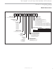
THE SMART SOLUTION FOR ENERGY EFFICIENCY Genesis Large (GL) Series R e v. : 1 3 A p r i l , 2 0 0 9 B GLH072-120, GLV160 Three Phase with CXM Schematic c l i m a t e m a s t e r.
C L I M AT E M A S T E R W AT E R - S O U R C E H E AT P U M P S Genesis Large (GL) Series R e v.
THE SMART SOLUTION FOR ENERGY EFFICIENCY Genesis Large (GL) Series R e v. : 1 3 A p r i l , 2 0 0 9 B GLV080-120 Three Phase with CXM Schematic c l i m a t e m a s t e r.
C L I M AT E M A S T E R W AT E R - S O U R C E H E AT P U M P S Genesis Large (GL) Series R e v.
THE SMART SOLUTION FOR ENERGY EFFICIENCY Genesis Large (GL) Series R e v. : 1 3 A p r i l , 2 0 0 9 B GLV200-300 Three Phase with CXM Schematic c l i m a t e m a s t e r.
C L I M AT E M A S T E R W AT E R - S O U R C E H E AT P U M P S Genesis Large (GL) Series R e v.
THE SMART SOLUTION FOR ENERGY EFFICIENCY Genesis Large (GL) Series R e v. : 1 3 A p r i l , 2 0 0 9 B Typical CXM w/ LON Schematic (GLV200-300 Shown) c l i m a t e m a s t e r.
C L I M AT E M A S T E R W AT E R - S O U R C E H E AT P U M P S Genesis Large (GL) Series R e v.
THE SMART SOLUTION FOR ENERGY EFFICIENCY Genesis Large (GL) Series R e v. : 1 3 A p r i l , 2 0 0 9 B GLV200-300 DXM w/Reheat c l i m a t e m a s t e r.
C L I M AT E M A S T E R W AT E R - S O U R C E H E AT P U M P S Genesis Large (GL) Series R e v. : 1 3 A p r i l , 2 0 0 9 B ClimaDry Modulating Reheat Option - GLV Unit Only - ClimaDry Sequence Of Operation A heat pump equipped with ClimaDry can operate in three modes, cooling, cooling with reheat, and heating. The cooling/heating modes are like any other ClimateMaster WSHP. The reversing valve (“O” signal) is energized in cooling, along with the compressor contactor(s) and blower relay.
THE SMART SOLUTION FOR ENERGY EFFICIENCY Genesis Large (GL) Series R e v. : 1 3 A p r i l , 2 0 0 9 B ClimaDry Modulating Reheat Option - GLV Unit Only • 2nd Stage Heating: A simultaneous call from (G), (Y1), and (Y2) to the (G), (Y1), and (Y2) terminals of the DXM control board will bring the unit on in 2nd Stage Heating. When the call is satisfied at the thermostat the unit will continue to run in 1st Stage Heating until the call is removed or satisfied, shutting down the unit.
C L I M AT E M A S T E R W AT E R - S O U R C E H E AT P U M P S Genesis Large (GL) Series R e v. : 1 3 A p r i l , 2 0 0 9 B ClimaDry Modulating Reheat Option - GLV Unit Only ClimaDry Application Considerations Unlike most hot gas reheat options, the ClimaDry option will operate over a wide range of EWTs. Special flow regulation (water regulating valve) is not required for low EWT conditions.
THE SMART SOLUTION FOR ENERGY EFFICIENCY Genesis Large (GL) Series R e v. : 1 3 A p r i l , 2 0 0 9 B Blower Adjustment method such as the Browning Belt Tensioner to set proper belt tension (See next page). CAUTION! Always disconnect all power supply(s) to unit prior to making belt or sheave adjustments. Inadvertently starting of the motor can cause damage to the equipment and personal injury.
C L I M AT E M A S T E R W AT E R - S O U R C E H E AT P U M P S Genesis Large (GL) Series R e v. : 1 3 A p r i l , 2 0 0 9 B Tensioning V-Belt Drives General rules of tensioning 1. Ideal tension is the lowest tension at which the belt will not slip under peak load conditions. 2. Check tension frequently during the first 24-48 hours of operation. 3. Over tensioning shortens belt and bearing life. 4. Keep belts free from foreign material which may cause slip. 5. Make V-drive inspection on periodic basis.
THE SMART SOLUTION FOR ENERGY EFFICIENCY Genesis Large (GL) Series R e v. : 1 3 A p r i l , 2 0 0 9 B Blower Sheave Information Table 4a: GLH Blower Sheave and Belt Information Model 072 096 120 Standard (hp) [kW] 1.5 [1.5] 2 [1.5] 2 [1.5] Large (hp) [kW] 2 [1.5] 3 [2.2] 3 [2.2] Standard Sheave (in) [cm] 1VP34 x 7/8 [2.22] 1VP56 x 7/8 [2.22] 1VP56 x 7/8 [2.22] Low Static Sheave (in) [cm] 1VP44 x 7/8 [2.22] 1VP56 x 7/8 [2.22] 1VP56 x 7/8 [2.
C L I M AT E M A S T E R W AT E R - S O U R C E H E AT P U M P S Genesis Large (GL) Series R e v. : 1 3 A p r i l , 2 0 0 9 B Blower Performance GL Series Dry Coil to Wet Coil Conversion Table Air Coil Face Velocity (fpm) Required BHP Multiplier Required RPM Multiplier 250 300 350 400 450 500 1.00 1.02 1.05 1.08 1.11 1.14 1.00 1.06 1.12 1.18 1.26 1.34 Example: GLV080 Dry coil performance is 0.92 BHP, 867 rpm @ 2600 cfm (or 2600 cfm / 9 ft2 coil = 290 fpm); Wet Coil performance would be 0.92 x 1.
THE SMART SOLUTION FOR ENERGY EFFICIENCY Genesis Large (GL) Series R e v. : 1 3 A p r i l , 2 0 0 9 B Blower Performance GLH 096 Blower Performance Airflow in CFM with dry coil and clean air filter. External Static Pressure (in. w.g.) Airflow (SCFM) 0.0 2600 0.1 0.2 0.3 0.4 0.5 0.6 0.7 0.8 0.9 1.0 1.1 1.2 1.3 1.4 1.5 BHP 0.84 0.91 0.97 1.04 1.10 1.17 1.24 1.31 1.37 1.44 1.51 1.58 1.65 1.
C L I M AT E M A S T E R W AT E R - S O U R C E H E AT P U M P S Genesis Large (GL) Series R e v. : 1 3 A p r i l , 2 0 0 9 B Blower Performance GLV 080 Blower Performance Airflow in CFM with dry coil and clean air filter. External Static Pressure (in. wg) Airflow (SCFM) 2000 2200 2400 2600 2800 3000 3200 BHP RPM Turns Open BHP RPM Turns Open BHP RPM Turns Open BHP RPM Turns Open BHP RPM Turns Open BHP RPM Turns Open BHP RPM Turns Open 0.0 0.1 0.2 0.3 0.4 0.5 0.6 0.7 0.8 0.9 1.0 1.
THE SMART SOLUTION FOR ENERGY EFFICIENCY Genesis Large (GL) Series R e v. : 1 3 A p r i l , 2 0 0 9 B Blower Performance GLV 120 Blower Performance Airflow in CFM with dry coil and clean air filter. External Static Pressure (in. wg) Airflow (SCFM) 0.0 2800 3000 3200 3400 3600 3800 4000 4200 4400 4600 BHP RPM Turns Open BHP RPM Turns Open BHP RPM Turns Open BHP RPM Turns Open BHP RPM Turns Open BHP RPM Turns Open BHP RPM Turns Open BHP RPM Turns Open BHP RPM Turns Open BHP RPM Turns Open 0.
C L I M AT E M A S T E R W AT E R - S O U R C E H E AT P U M P S Genesis Large (GL) Series R e v. : 1 3 A p r i l , 2 0 0 9 B Blower Performance GLV 200 Blower Performance Airflow in CFM with dry coil and clean air filter. External Static Pressure (in. wg) Airflow (SCFM) 0.0 5400 5800 6200 6600 7000 7400 7800 8200 BHP RPM Turns Open BHP RPM Turns Open BHP RPM Turns Open BHP RPM Turns Open BHP RPM Turns Open BHP RPM Turns Open BHP RPM Turns Open BHP RPM Turns Open 0.82 550 4.5 0.93 570 4 0.1 0.
THE SMART SOLUTION FOR ENERGY EFFICIENCY Genesis Large (GL) Series R e v. : 1 3 A p r i l , 2 0 0 9 B Blower Performance GLV 300 Blower Performance Airflow in CFM with dry coil and clean air filter.o e e o a ce G 0.0 7400 7800 8200 8600 9000 9400 9800 10200 10600 Co External Static Pressure (in. wg) Airflow (SCFM) BHP RPM Turns Open BHP RPM Turns Open BHP RPM Turns Open BHP RPM Turns Open BHP RPM Turns Open BHP RPM Turns Open BHP RPM Turns Open BHP RPM Turns Open BHP RPM Turns Open 300 1.
C L I M AT E M A S T E R W AT E R - S O U R C E H E AT P U M P S Genesis Large (GL) Series R e v. : 1 3 A p r i l , 2 0 0 9 B Unit Starting & Operating Conditions Operating Limits Environment – This unit is designed for indoor installation only. Power Supply – A voltage variation of +/– 10% of nameplate utilization voltage is acceptable.
THE SMART SOLUTION FOR ENERGY EFFICIENCY Genesis Large (GL) Series R e v. : 1 3 A p r i l , 2 0 0 9 B Unit & System Checkout lons [1/2 kg per 750 L] of water (or other equivalent approved cleaning agent). Reset the boiler to raise the loop temperature to about 100°F [38°C]. Circulate the solution for a minimum of 8 to 24 hours. At the end of this period, shut off the circulating pump and drain the solution. Repeat system cleaning if desired. 8.
C L I M AT E M A S T E R W AT E R - S O U R C E H E AT P U M P S Genesis Large (GL) Series R e v. : 1 3 A p r i l , 2 0 0 9 B Unit Start Up Procedure WARNING! WARNING! When the disconnect switch is closed, high voltage is present in some areas of the electrical panel. Exercise caution when working with energized equipment. 6. WARNING! WARNING! Verify ALL water controls are open and allow water flow prior to engaging the compressor.
THE SMART SOLUTION FOR ENERGY EFFICIENCY Genesis Large (GL) Series R e v. : 1 3 A p r i l , 2 0 0 9 B Unit Start Up Procedure Table 7. Coax Water Pressure Drop Model GPM GLH096 Pressure Drop CXM/DXM Safety Control Reset Lockout - In Lockout mode, the Status LED will begin fast flashing. The compressor relay is turned off immediately. Lockout mode can be soft reset via the thermostat “Y” input or can be hard reset via the disconnect.
C L I M AT E M A S T E R W AT E R - S O U R C E H E AT P U M P S Genesis Large (GL) Series R e v. : 1 3 A p r i l , 2 0 0 9 B Unit Operating Conditions Table 8: Typical Unit Operating Pressures and Temperatures o o o o o Table 9: Water Temperature Change Through Heat Exchanger 54 Water Flow, gpm [l/m] Rise, Cooling °F, [°C] Drop, Heating °F, [°C] For Closed Loop: Ground Source or Closed Loop Systems at 3 gpm per ton [3.9 l/m per kW] 9 - 12 [5 - 6.7] 4-8 [2.2 - 4.
THE SMART SOLUTION FOR ENERGY EFFICIENCY Genesis Large (GL) Series R e v. : 1 3 A p r i l , 2 0 0 9 B Preventive Maintenance Water Coil Maintenance – (Direct Ground Water Applications Only) If the installation is performed in an area with a known high mineral content (125 P.P.M. or greater) in the water, it is best to establish with the owner a periodic maintenance schedule so the coil can be checked regularly.
C L I M AT E M A S T E R W AT E R - S O U R C E H E AT P U M P S Genesis Large (GL) Series R e v.