
System information
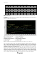


C0240111-06-07-GB
18
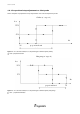
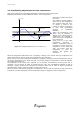
s e t p o i n t
s e t p o i n t
+
p r o p o r t i o n a l b a n d
s t a r t c o m p r e s s o r 1
t [ m i n ]
T i n [ ° C ]
O F F
O N
m a x
m i n
P a s s [ K w ]
B
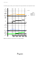
Figure 1.11 c)
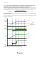
Suppose we have a unit with more than one compressor.
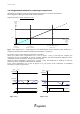
Set point + Banda
proporzionale (100 %)
2x Min
Max
% accensione
2° compressore
Min
% accensione
1° compressore
Potenza
richiesta del
termoregolatore
[%]
Potenza
assorbita
[Kw]
set point
(0%)
Figure 1.12: Adjustment for a twin-compressor unit. Min=theoretical minimum electrical power absorbed by a
compressor, Max=theoretical maximum electrical power absorbed by a compressor.
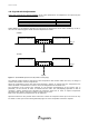
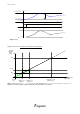
Absorbed
power
[Kw]
%
compressor 1
switch-on
%
compressor 2
switch-on
Set point + prop.
band (100 %)
Thermoregulator power
Request [%]