
System information


C0240111-06-07-GB
21
2 ALARMS
Press the [ALARM] key once to enter the “alarms menu” and view the alarm message along with its code.
If there is more than one alarm, scroll the menu using the [UP] and [DOWN] keys.
In the W3000 base, “NO A” is displayed if there is no alarm, otherwise the alarm code appears.
Press any other key to exit from this menu.
To reset the alarm press the [ALARM] key again and hold it down until the message “No Alarm Active”
(for W3000 or W3000 compact) or “No A” (for W3000 base) appears. If the message does not appear it
means that one or more alarm conditions are still active.
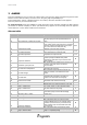
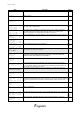
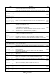
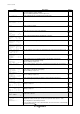
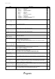
Alarms table
ALARM DESCRIPTION details RESET
002
Phase sequence / Voltage out of range
Faulty phase connection. Totally shuts down the
unit (only displayed if the input that detects it is
fitted)
A
003
Evaporator flow switch
No flow to evaporator. The alarms automatically
resets 3 times in the same hour if flow is restored
within the maximum operating time of the pumps
with a small amount of water (P23.34),
otherwise, it must be reset manually
A/M
005
Low inlet temperature
Enabled only in the “heat pump” mode. Low
water temperature at evaporator inlet.
S-A
006
High inlet temperature
Enabled only in the “chiller” mode. High water
temperature at evaporator inlet.
S-A
010
Evaporator antifreeze
Low water temperature at evaporator outlet.
Also
specifies (except for W3000 base) which
evaporator (if more than one) is involved in the
alarm condition.
M
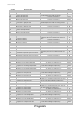
014
Insufficient system pressure
Only displayed if the relative input is present (see
I/O menu). Unit stops due to an external
pressure switch.
M
017
Low external air temperature
Indicates that the external air temperature has
fallen below the set point.
S
021
Low water charge
The evaporator inlet temperature changes too
quickly and creates a low water level in the
system.
S
022
Low water flow
The temperature difference between the
evaporator inlet and outlet is too high and
creates a low water flow from the pump
M
045
Condenser flow switch
Similarly to “Evaporator flow switch” (only for
water/water units with freon reversal).
A/M
046
Recuperator flow switch No water flow to the recuperator. A
051
Pump 1 maintenance
Maintenance hours limit exceeded (in units with
just 1 pump, pump 1 is the evaporator pump)
S
052
Pump 2 maintenance
Pump 2 maintenance hours limit exceeded (in
units with more than one pump).
S
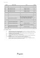
061
Subcooling driver 1 offline
The circuit 1 subcooling management driver is
disconnected (only for units with centrifuge
compressors)
A
062
Subcooling driver 2 offline “as above, for circuit 2” A
063
Subcooling driver 3 offline “as above, for circuit 3” A
064
Subcooling driver 4 offline “as above, for circuit 4” A
075
Condenser antifreeze
Low water temperature at condenser outlet.
Except for W3000 base, it also specifies which
condenser (if more than one) is involved in the
alarm condition (only for water/water units with
freon reversal).
M
076
Recuperator antifreeze Low water temperature at recuperator outlet. A
081
Pump 1 thermal switch
Pump 1 overheated (in units with just 1 pump,
pump 1 = evaporator
pump)
M