
Parts List
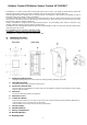


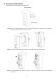

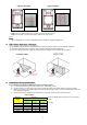
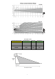
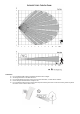


Table Of Contents

DIP
Position
Function
Switch1
ON
Test Mode
OFF
Normal Mode (default)
Switch2
ON LED Indicator Enable (default)
OFF
LED Indicator Disable
Switch3
ON
Vertical Curtain IR Detection
(default)
OFF Horizontal Curtain IR Detection
Switch4
ON
Reserved
OFF Reserved
DIP
Position
Function
Switch5
ON
Reserved
OFF
Reserved
Switch6
ON
Reserved
OFF
Reserved
Switch7
ON
Reserved
OFF
Reserved
Switch8
ON
Reserved
OFF
Reserved
LED Indicator
When enabled, the LED Indicator will light up in the following conditions:
When the Tamper Switch is triggered, the LED will flash for 6 times to indicate it is transmitting “Tamper” signal.
When the PIR Camera is in fault conditions (tamper open or low battery condition persists), each time it transmits a
detected movement, the LED will flash for 6 times.
After the Test button is pressed once to enter Test Mode, the LED will flash for 60 seconds to indicate that the PIR
motion sensor camera is warming up.
In Test mode, the LED will turn on for 2 seconds whenever a movement is detected.
If the LED flashes to indicate signal transmission, it will flash twice rapidly upon receiving acknowledgement from panel.
<
<
N
N
O
O
T
T
E
E
>
>
The LED indicator can be enabled by setting the DIP Switch 2 to ON position. Please refer to DIP Switch Position
Table for details.
Image Capture
When the alarm system is armed, the PIR Camera will capture 1, 3 or 6 alarm images in 640 x 480 or 320 x 240 resolutions
(programmable from Control Panel) upon movement detection. You can also manually request the PIR Camera to take a
picture through the Control Panel. The captured images will be transferred to the Control Panel for visual alarm verification.
Warm Up Period
The PIR Camera will warm up for 60 seconds in the following conditions:
When the PIR Camera is turned on by the Control Panel system upon entering arm mode (either with or without fault
conditions).
When the test button is pressed once to enter Test Mode.
The Red LED will flash slowly during warm up period. During the 60-second warm up period, the PIR Camera will not be
activated.
Test Mode
The PIR Camera can be put into Test mode for 10 minutes by pressing the Test button once. In Test mode, the sleep
timer and image capture functions are disabled. LED indicator is enabled to light up for two seconds whenever a
movement is detected. The PIR Camera will automatically exit Test Mode after 10 minutes, and return to normal mode.
To put the PIR Camera into constant Test mode, please adjust DIP switch 1 to ON position (Please refer to DIP Switch
Position Table).
Supervision Signal
After installation, the PIR Camera will automatically transmit Supervisory signals periodically to the Control Panel at
random intervals of 90 to 110 minutes.
If the Control Panel has not received the signal from the PIR Camera for the preset period of time, the Control Panel will
indicate on its display that the particular PIR Camera is experiencing an out-of-signal problem.
Sleep Timer
The PIR Camera features an automatic “sleep time” of approximately one minute for power conservation. After
transmitting a detected movement, the PIR Camera will not retransmit for one minute. Any further movement detected
within this one-minute sleep period will extend the sleep time by another minute. This way, continuous movement in
front of PIR Camera will not unduly exhaust the battery.
Tamper Protection
The PIR Camera is protected by an internal tamper switch which is compressed when the PIR Camera is hooked onto
the mounting bracket. When the PIR Camera is removed from the mounting bracket, the tamper switch will be activated
and the PIR Camera will send a tamper open signal to the control panel to remind the user of this condition.
DIP Switch Position Table
The function of each DIP Switch is listed in the table below. The DIP Switch is either ON or OFF. Top position indicates ON
and bottom position indicates OFF.
ON
OFF
2