
User's Manual


Installation
Wiring
WARNING
Wiring of the device should only be performed by a licensed electrician. The circuit box’s main breaker
should be turned off to perform installation.
The insertion hole wire specification is AWG18 or Ø 1.02 (mm²).
The Clamp specification is 60A Ø10mm
Please make sure the main power in your facility is also off before installing. Follow the steps below:
1. Connect AC Input cable to a socket near the Electrical Box to power on the Clamp Meter.
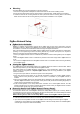
2. Attach both ends of the Current Transformer Cables first as picture shown below. Once you have attached
the Current Transformer Cable, start spinning the waterproof latch clock-wise until you have tighten and
secure both ends of the Current Transformer Cable.
3. Open the clamp as indicated by below picture. The clamp should be applied onto an electic cable The
arrow direction on the clamp need to point at the correct direction of the electricity current flows (K
L). If
arrow is faced in reverse direction, the reading will display negative value (-) however it will not influence
the readings.
4. Follow the schematics below as an example; clip the clamps on the electricity cables on the 2 the
incoming power cable connected to the Main Circuit Breaker.
K
L