
Installation Instructions

2
DIP Position Function
Switch1
ON Test Mode
OFF Normal Mode (default)
Switch2
ON
Reserved
OFF
Switch3
ON PIR facing a wall within 10 m
OFF
PIR facing an open space
(no wall within 10 m)(default)
Switch4
ON PIR facing a lawn (default)
OFF
PIR facing a concrete/stone
ground
DIP Sensitivity Level
Switch5 Switch6
ON ON Low; 75 cm/60 kg pet (default)
ON OFF Medium; 50 cm / 35 kg pet
OFF ON High; 30 cm / 20 kg pet
OFF OFF Reserved
DIP Position Function
Switch7
ON Double Knock Enable (default)
OFF Double Knock Disable
Switch8
ON Pet Immune Enable (default)
OFF Pet Immune Disable
When the Tamper Switch is triggered, the LED will flash to indicate it is transmitting “Tamper” signal.
When the Tamper condition persists, each time it transmits a detected movement, the LED will flash.
In Test mode, the LED will flash whenever a movement is detected.
The LED will not flash if the EIR tamper and battery are normal and is not under test mode.
If the LED flashes to indicate signal transmission, it will flash twice rapidly upon receiving acknowledgement from
panel.
T
T
e
e
s
s
t
t
M
M
o
o
d
d
e
e
The Motion Sensor can be put into Test mode for 10 minutes by pressing the Test button once. In Test mode, sleep timer is
disabled and LED indicator is enabled to light up for two seconds whenever a movement is detected. The Motion Sensor
will automatically exit Test Mode after 10 minutes, and return to normal mode.
To put the Motion Sensor into constant Test mode, please adjust DIP switch 1 (Please refer to DIP Switch Position Table).
B
B
a
a
t
t
t
t
e
e
r
r
y
y
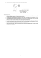
The Motion Sensor uses two AAL91 lithium batteries as its power source.
The Motion Sensor features low battery voltage detection. When low battery is detected, a low battery signal will be
sent to the Control Panel along with regular signal transmissions for the Control Panel to display the status accordingly.
To Change Battery:
Step 1: Navigate the Control Panel into Programming mode.
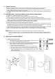
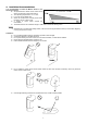
Step 2: Remove the Motion Sensor from mounting position and unscrew to open top cover.
Step 3: Remove the old batteries and press the tamper button a few seconds to fully discharge.
Step 4: Insert two new AAL91 lithium batteries.
Step 5: Screw back the top cover.
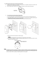
Step 6: Mount back the Motion Sensor to mounting location.
Step 7: Navigate the Control Panel to exit Programming mode and return to operation mode. The procedure is complete.
S
S
u
u
p
p
e
e
r
r
v
v
i
i
s
s
o
o
r
r
y
y
S
S
i
i
g
g
n
n
a
a
l
l
After installation, the Motion Sensor will automatically transmit Supervisory signals periodically to the Control Panel at
random intervals of 15 to 18 minutes.
If the Control Panel has not received the signal from the Motion Sensor for the preset period of time, the Control Panel
will indicate on its display that the particular Motion Sensor is experiencing an out-of-signal problem.
S
S
l
l
e
e
e
e
p
p
T
T
i
i
m
m
e
e
r
r
The Motion Sensor features an automatic “sleep time” of approximately one minute for power conservation. After
transmitting a detected movement, the Motion Sensor will not retransmit for one minute. Any further movement detected
within this one-minute sleep period will extend the sleep time by another minute. This way, continuous movement in front of
Motion Sensor will not unduly exhaust the battery.
D
D
o
o
u
u
b
b
l
l
e
e
K
K
n
n
o
o
c
c
k
k
F
F
u
u
n
n
c
c
t
t
i
i
o
o
n
n
The Motion Sensor has a double knock function. If the double knock function is enabled, the Motion Sensor will report an
alarm to the control panel only if two movements are detected within 10 seconds. If the double knock function is disabled,
the Motion Sensor will report an alarm to the control panel when a movement is detected.
P
P
r
r
o
o
x
x
i
i
m
m
i
i
t
t
y
y
D
D
e
e
t
t
e
e
c
c
t
t
i
i
o
o
n
n
The Motion Sensor has a digital proximity detector that can detect any masking (blocking) attempt by an intruder.
When a masking event is detected, and the masking condition lasts for 2 minutes, EIR-32 will send tamper open signal
to the Control Panel to notify user of the condition.
After masking/blocking is removed for 2 minutes, EIR-32 will send tamper restore signal to the Control Panel.
<
<
N
N
O
O
T
T
E
E
>
>
Any IR trigger movement will clear currently detected masking event/condition. A masking event must be detected
and last for 2 minutes for the tamper open report to be tramsmitted.
D
D
I
I
P
P
S
S
w
w
i
i
t
t
c
c
h
h
P
P
o
o
s
s
i
i
t
t
i
i
o
o
n
n
T
T
a
a
b
b
l
l
e
e
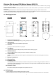
The function of each DIP Switch is listed in the table below. The DIP Switch is either ON or OFF. Top position indicates ON
and bottom position indicates OFF.
<NOTE>
After changing Dip Switch settings, please re-power on EIR-32 for it to operate with new Dip Switch Settings.
ON
OFF