
Installation Instructions

3
Tamper Protection
EIR-32 is protected by a tamper switch which is compressed when it is hooked onto the mounting bracket.
Whenever the Motion Sensor is removed from the mounting plate, the tamper switch will be activated.
When the Motion Sensor is forcibly removed from mounting location, the Break Away area on the mounting plate will
detach, also allowing the tamper switch to be activated.
The Motion Sensor will send a tamper open signal to remind the user of the condition whenever the tamper switch is
activated.
G
G
e
e
t
t
t
t
i
i
n
n
g
g
S
S
t
t
a
a
r
r
t
t
e
e
d
d
–
–
L
L
e
e
a
a
r
r
n
n
i
i
n
n
g
g
t
t
h
h
e
e
M
M
o
o
t
t
i
i
o
o
n
n
S
S
e
e
n
n
s
s
o
o
r
r
i
i
n
n
t
t
o
o
t
t
h
h
e
e
C
C
o
o
n
n
t
t
r
r
o
o
l
l
P
P
a
a
n
n
e
e
l
l
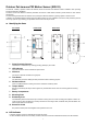
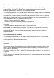
Loosen the fixing screws and remove the cover assembly.
Based on your needs, set Sensitivity Switch as shown in DIP Switch Position Table.
Insert two AAL91 lithium batteries into the battery holder taking care to connect the polarity correctly.
The LED indicator will flash for 60 seconds. The Motion Sensor is warming up. During the warming period, the Motion
Sensor is not activated. It is recommended that you stay away from the detection area during this time. After the
warming period is over, the LED dims and the Motion Sensor is ready to operate.
Put the Control Panel into learning mode, refer to Control Panel manual for details.
Press the Test button once. The LED indicator will flash for three times.
If the Control Panel receives the signal, it will display the information accordingly. Refer to the Control Panel manual to
complete the learn-in process. (For certain Control Panel models, the Motion Sensor can be learnt in as a regular PIR
with programmable attributes and thus the Control Panel will report when an alarm is triggered).
After the Motion Sensor is learnt-in, put the Control Panel into Walk Test mode. Hold the Motion Sensor in the desired
location, and press the Test button to confirm this location is within the signal range of the Control Panel.
When you are satisfied that the Motion Sensor works in the chosen location, you can proceed to installation.
<
<
N
N
O
O
T
T
E
E
>
>
Walk Test should be conducted to confirm proper operation and coverage of the Motion Sensor.
When learning Motion Sensor or conducting Walk Test, please avoid obstructing the anti-masking detector by
your hand, otherwise tamper open signal will transmitted to the Control Panel if masking condition lasts for 2
minutes.
M
M
o
o
u
u
n
n
t
t
i
i
n
n
g
g
&
&
I
I
n
n
s
s
t
t
a
a
l
l
l
l
a
a
t
t
i
i
o
o
n
n
M
M
e
e
t
t
h
h
o
o
d
d
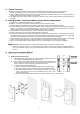
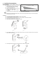
Mounting with mounting plate:
The Motion Sensor is designed to be mounted on either a flat surface or in a
corner situation with fixing screws and plugs provided.
The provided mounting plate has knockouts, where the plastic is thinner and
can be broken for mounting purpose. Two knockouts are for surface fixing
and four knockouts are for corner fixing as shown in the picture.
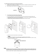
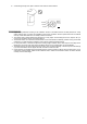
To Mount EIR-32 with Mounting Bracket:
1) Use the mounting plate as a template to drill holes on the wall for plugs.
2) Push in the plugs and fix the mounting plate on the wall with the screws.
3) Mount EIR-32 with the hooks of the mounting plate latched on the back
cover of the EIR-32, and then push downwards until you hear a click
sound to lock the hook.
4) Insert the protective shield (the protective film from both sides must first be removed).