
User's Manual


2
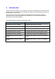
2. Panel Information
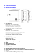
2.1. Identifying the parts:
1 LED 1 (Red/Green)
Red LED ON – Area 1 in Full Arm Mode.
Red LED Flash – Area 1 in Home 1/2/3 Mode.
Green LED ON - System in the learning mode.
Green LED Flash - System in the Walk Test mode.
2 LED 2 (Red/Green)
Red LED ON – Area 2 in Full Arm mode
Red LED Flash – Area 2 in Home 1/Home 2/Home 3 mode
Green LED On – System in the learning mode
Green LED Flash – System in the Walk Test mode
3 LED 3 (Red/Yellow)
Red LED ON – Alarm in memory.
Red LED Flash – Alarm
Yellow LED ON – system fault
4 Top Fixing Screw x 2 (for Version A only)
5 Buzzer
6 Bottom Fixing Screw x 2
7 Micro SIM Card Compartment
8 USB Port
9 Learn/ResetButton
10 Ethernet Port (pre punched hole for Version B only)
11 Battery Switch (slide to “ON” to meet requirements of the applicable EN standard.)
12 DC Jack
13 Pre Punched Hole for Wiring (for Version A only)