
Installation Instructions

2
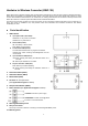
Power Supply
Power on the HWC-1B by connecting the two-wired 12V AC-DC Adaptor to the +12V/GND terminal.
HWC-1B will charge the rechargeable battery pack automatically when power is supplied and the rechargeable
battery pack is connected. When power supply is interrupted, HWC-1B will switch to using the rechargeable
battery and continue operation.
When power supply is interrupted and restore, HWC-1B will transmit AC failure and restore signal respectively.
HWC-1B can supply 12V, 100mA power to connected devices via the power terminal.
Rechargeable Battery Pack
A 1.2V*8 750mAh AAA Ni-MH Rechargeable Battery Pack is installed inside HWC-1B to serve as a backup in
case of a power failure. The battery pack is not connected by factory. Please connect the battery pack if you want
to use it as backup power.
HWC-1B will charge the battery automatically when power is connected. When power supply is interrupted,
HWC-1B will switch to using the rechargeable battery and continue operation.
When the rechargeable battery is low on power, HWC-1B will transmit low battery signal. When the battery has
been charged, HWC-1B will transmit battery restore signal
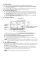
Application Diagram
The Power Terminal (Z1~Z9 zones) inputs allow existing wired sensors to be connected to the HWC-1B Converter:
Each input zone is only available to one wired sensor.
It is essential for all input zones that are used to have an EOL resistor (with a value from 1k to 10k ohms).
Keep the existing installation zones which already have EOL resistor (with a value from 1k to 10k ohms).
For a NC loop without an EOL resistor, please add one in series with the loop.
For a NO loop without an EOL resistor, please add one in parallel (across) the loop. It should be located at the end
of the loop far away from the Control Panel.
<
<
N
N
O
O
T
T
E
E
>
>
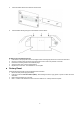
If you wish to change the wires on the input zone, please power OFF HWC-1B first, then change wire input
location as prefered and power ON the HWC-1B again. Press the calibration button to finalize the changing
process.
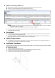
(SW12) Calibration Button
After wiring existing sensors to the HWC-1B, initiate the calibration process which allows the HWC-1B to learn which zone
will be active and what EOL resistors are used. Any unused / opened zone will not be recognized and reported to the
Control Panel.
Ensure all zones are well connected.
Press and hold the Calibration button (SW12) for 2 seconds. Both LED4 (Green) and LED5 (Red) will turn ON.
When calibration is completed, LED5 (Red) will turn OFF. LED4 (Green) will stay ON to indicate calibration is
successful.
When calibration fails, LED4 (Green) will turn OFF, LED5 (Red) will flash to indicate error.
<
<
N
N
O
O
T
T
E
E
>
>
Zone 1 must be wired for HWC-1B to function normally and use calibration function.