August 15, 2013
Table of Contents 1. 2. INTRODUCTION ..................................................................................................................1 1.1. THE MX MEDICAL AND INTRUSION ALARM SERIES .............................................................1 1.2. WHAT’S IN THE BOX ..............................................................................................................2 SYSTEM OVERVIEW ............................................................................................
7. 6.1.3. Arming/Disarming the System ...............................................................................97 6.1.4. Voice Prompts ............................................................................................................99 6.1.5. Walk Test (Range Test)...........................................................................................100 6.1.6. Factory Reset............................................................................................................
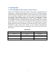
1. Introduction 1.1. The MX Medical and Intrusion Alarm Series Climax’s MX Medical and Intrusion Alarm Series marks a watershed in the evolvement of medical alarm systems. One of the first of Climax’s wireless medical alarms to be integrated with an intrusion alarm system, the MX Series not only provides thorough care for your loved ones at home but also protects your house and property when you are away.
1.2.
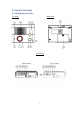
2. System Overview 2.1.
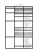
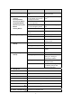
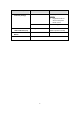
Control Panel Definitions Button/LED/Component 1 2 Red Help Button Red Backlight Behavior Function/Indication Pressed in idle/normal mode Pressed once in learning mode Pressed for 3 seconds in learning mode Dimly lit Blinking To summon emergency help To select Pendant #2 Brightly illuminating 3 Green Reset Button Pressed in idle/normal mode Pressed once before the Control Panel dials out for alarm reporting Pressed once during or at the end of a two-way communication Pressed for 3 seconds in idl
Button/LED/Component Behavior Function/Indication 4 Green Backlight Blinking (on MX-2 and MX-6 only) The Control Panel has a phone line fault.
Button/LED/Component 18 GPRS/GSM or 3G Fault Indicator (orange) Behavior On Function/Indication Failed registration ) Registration will fail when an AC power failure occurs. Successful registration Off 19 GPRS/GSM or 3G Status Indicator (red) 20 GPRS/GSM or 3G Reset Button 21 SIM Card Base Blinking Pressed for one second When the GPRS/GSM or 3G module operates normally To reset GPRS/GSM or 3G Insert your SIM card in this slot.
2.2. Power Supply z Plug the AC power adapter into the Control Panel’s DC jack and connect to the mains power. Make sure that you use an adapter with the appropriate AC voltage rating to prevent component damage. An AC-DC 12V/2A switching power adapter is generally used to power the standard version of the Control Panel. z In addition to the AC power adapter, a rechargeable battery is installed inside the Control Panel to serve as a backup in case of a power failure.
3. Installing MX Step 1. Choose a suitable location for the Control Panel. The Control Panel requires the mains power and PSTN (MX-2 and MX-6), GSM/3G (MX-3 and MX-8) and/or Ethernet (MX-6 and MX-8) connections and should be easily accessible. It should not be placed in a damp location such as a bathroom or close to a heat source like a microwave oven, which could reduce signal strength. Step 2. Plug the USB cable into the Control Panel’s USB port and connect it to a PC for MX programming. Step 3.
4. Programming MX 4.1. PC Programming 4.1.1. Installing USB Driver Please first install the USB Driver provided in your CD-ROM on your PC. ) It is recommended that you use Windows XP or Windows 7 operating systems. Step 1. Plug the USB cable into the Control Panel’s USB port and connect it to a PC. Step 2. Insert the supplied CD-ROM into your CD-ROM drive and find the “USB Driver” folder (you may copy and paste the folder to your desktop for later use).
Step 3. Click on the “Device Manager” icon and find “MOBIL PERS BASE ISP” under “Other devices.” Click “Update Driver.
Step 4. When the Hardware Update Wizard window pops up, select “Install from a list or specific location (Advanced)” and click “Next.
Step 5. Search for the USB Driver folder. If you have copied and pasted the USB Driver folder to your desktop, tick “Include this location in this search” and click “Browse.” Step 6. Select the “USB Driver” and click “OK.
Step 7. It takes a short while for your PC to install the USB Driver. If the Hardware Installation warning window pops up, please click “Continue Anyway.
Step 8. When the installation has been completed, click “Finish” on the Hardware Update Wizard window to close the wizard.
Step 9. Please remember the COM port number of MX as shown in the “Device Manager” section. You will need the COM port number when doing PC programming. Now that the USB Driver has been successfully installed, you can proceed with PC programming of MX.
4.1.2. PC Programming Tool You can easily configure the Control Panel via the PC Programming Tool provided in the CD-ROM. Step 1. Find and open the “PC Programming Tool” folder in the supplied CD-ROM. Click “MPTool_x.xx.exe” to execute the programming tool. The following configuration screen will be opened.
Step 2. Select the following settings in the top section of the configuration screen and click “Open.” z z z z z z Port: Select the COM port generated for MX after installing the USB Driver (the USB port connected to MX).
Step 3. Enter SMS Keyword and Access Code and click “Read.” When a pop-up window shows “Read configuration success,” the configuration page below will be opened and you can proceed with the programming of MX.
Step 4. SMS Program Click “SMS Program” to set a SMS Keyword (15 characters max.) and a PIN Code (4-8 digits) and click “Write.” Please note that the SMS Keyword is case-sensitive. ) The version of your MX model will be shown on the top of the screen.
Step 5. APN Click “APN” to set APN Name, APN User and APN Password and click “Write.” z Access Point Name (APN): The name of an access point for GPRS. Please ask your SIM card service provider for your APN. z Username: Offered by your SIM card service provider. Please ask your service provider for your GPRS username. If no username is required, you may skip this step. z Password: Offered by your SIM card service provider. Please ask your service provider for your GPRS password.
Step 6. Reporting Click “Report” to program destinations of reporting, event filters (Event), reporting formats (Type), follow-on options (Follow-on) and reporting sequence (Group 1~5) for alarm reporting and status reporting. Click “Write” after you have completed the settings. z Destinations of reporting 1~8: Program destinations of reporting 1~8 in the No. 1~No. 8 boxes. z Event: Event filters have five options, “All,” “Medical,” “Emergency,” “Status” and “Burglar.
z Group 1~Group 5: Groups 1~5 determine the sequence of reporting. The reporting sequence goes from Group 1 to Group 5. The procedure and details of programming are as follows: 1. Programming destinations of reporting: You can set 8 destinations of reporting. To program destination 1, please first enter its reporting number/setting in the No. 1 box and select its reporting format under “Type” as well as its follow-on option under “Follow-On.” Configure destinations 2-8 in the same manner.
process events according to the categories to which they belong. Please refer to “Appendix 7.1.9. Contact ID Event Codes” to check out the categories to which events are assigned. Events are divided into four categories: medical, emergency, status and burglary. If the option “all” is selected for a destination, all events will be reported to this destination. Examples are as follows: - A device low on battery is a “status” event.
Therefore, the system will skip the rest of the destinations in this group and go on reporting to the next group. For example, if destinations 2, 4 and 7 are assigned to Group 3 and the system has successfully reported to destination 2, the system will skip destinations 4 and 7 and go on reporting to Group 4.
Step 7. Non-Emergency Call z Click “Non-Emergency Call” to program the non-emergency call number and click “Write.” z When the Control Panel is in normal mode, you can make a non-emergency call by pressing the green reset button for 3 seconds or press the yellow button once (if the yellow button has been programmed as a non-emergency call button). The Control Panel will emit 2 beeps and automatically dial the programmed non-emergency call number for two-way communication.
Click “Setting” to program “Guard Time Normal,” “Guard Time for Fall Sensor,” “Auto Check-In Interval,” “Auto Check-in Offset,” “Yellow Away/Home Button,” “Inactivity Timer,” “Inactivity Interval,” “Inactivity Warning Time,” “Callback Timer,” “Two-Way Timer,” “Supervision Timer Interval” and “Speaker Volume Two-Way,” “Speaker Volume Talk Only,” “Speaker Volume Other,” Sound Setting Guard Beep,” “Sound Setting Confirm Beep,” “Answer Incoming,” “Alarm Length,” “Exit Time” and “Entry Time.
zYou can set a guard time period for Fall Sensor. A voice prompt announcing “a fall has been detected” will be played every 2-3 seconds during Fall Sensor’s guard time. zIf a false alarm is triggered by Fall Sensor, it can be canceled within the guard time period. zThis function is used when a fall is detected. 3. Auto Check-In Interval: zYou can select the length of the interval between auto check-in reports. zThere will be no auto check-in report if you select “Disable.
zAs an away/home button: The user can use the away/home button to toggle on/off the inactivity timer. When the user presses the away/home button to toggle off the inactivity timer before leaving home, the CID event code 666 with the prefix “1” will be reported to the CMS and two-way communication will be opened after the reporting.
enabled, the user can stop the inactivity timer when arming his house and restart the inactivity timer when disarming his house. ) Please set the inactivity timer as “off” if you program the yellow button as a non-emergency call button or a security button. 7. Inactivity Interval: zThis function monitors user movements and sends an inactivity report to the CMS if the user fails to reset the inactivity timer before the interval expires.
CMS directly. You can communication methods. use DTMF commands to switch z The Access Code must be entered within 15 seconds, otherwise the system will disconnect the call automatically. z Press DTMF (9) or the reset button on the Control Panel to terminate the call. z When callback time is up, the system will automatically exit the waiting mode and return to idle mode. z The callback function is automatically disabled during an AC power failure period. 10.
beeping sound during guard time. 16. Sound Setting Confirm Beep: z Select “on” to enable confirmation beeps during reporting or “off” to disable confirmation beeps during reporting. 17. Answering Incoming [Calls]: z When this function is set as “on,” the Control Panel rings for incoming calls. You can answer an incoming call by pressing the red help button on the Control Panel. z When this function is set as “off,” the Control Panel remains silent during incoming calls.
Step 9. z Click “Network” to configure networking settings. z Select “Enable” or “Disable” for the DHCP setting: Enable: Select “Enable” if a DHCP server is present to enable settings to be automatically assigned from the server. If you select “Enable,” you can skip the “IP Address,” “Subnet Mask,” “Default Gateway” and “Default DNS” settings. These settings will be automatically assigned. Click “Write” directly after you have selected “Enable” for the DHCP setting.
Step 10. Sensors 1. Viewing the data of sensors: When you have learned sensors into the Control Panel via the local learning method (see 5.1. Learning in Pendant #1, Pendant #2 and Other Devices), you can click “Sensors” and “Read” to view the zone numbers, types, battery status, tamper conditions, operating status and sound attributes of all of the sensors that have been learned in.
2. Adding sensors: zIn addition to the local learning method, you can also use the “Add Sensor” section on the “Sensors” page to learn sensors into the Control Panel. zEnter the zone number (Zone 1~Zone 100) to which you wish to assign a sensor and the Sensor ID, which is the barcode on the back of the sensor, and click “Add Sensor.” You can enter 1~100 in the zone number box.
3. Editing and removing sensors: z Editing the sound attribute of a sensor: Click any box in the section of the sensor that you wish to configure. For example, if you wish to edit the sound attribute of the sensor in Zone 3, you can click any box in the Zone 3 section. The “Dialog” pop-up window will be shown. If you want the sensor in Zone 3 to be silent, tick “Silent” and “Edit.” If you don’t want the sensor to be silent, leave the box in front of “Silent” blank and tick “Edit.
Step 11. System When you click “System” to enter the “System” screen, you can carry out the following operations: 1. Rebooting the Control Panel: zYou can click “Reboot Base” to reboot the Control Panel. The Control Panel will emit 2 beeps about 2 seconds after you click the “Reboot Base” button. The following screen will be automatically closed and you will need to restart the PC Programming Tool for further operation.
2. Rebooting GSM: zIf this command is successful, the message “ RSTG” will be shown at the bottom left-hand corner of the screen.
3. Checking the condition of the Control Panel: zYou can click “Alive” to check if the Control Panel can respond to your commands properly. zIf the Control Panel responds properly, the message “ ECHO” will be shown at the bottom left-hand corner of the screen.
4. Restoring the system to factory settings: zYou can click “Factory Reset” to restore the system to factory settings. The system will immediately restore all programmed parameters to factory settings and the Control Panel will emit 2 beeps after you click the “Factory Reset” button. zIf you want to keep your network settings and/or device settings, please click the box(s) before these specifications before clicking “Factory Reset.
5. Selecting an event code: zYou can select the event code to be sent to the CMS when the red button of the Control Panel is pressed. Choose your preferred event code in the box after “Help Event” and click “Write.
6. Jamming reports: z You can select to enable or disable jamming reports. Select your setting in the box after “Jamming Report” and click “Write.” z Jamming reports can only be sent in the CID format and not in the Scancom or Tunstall format.
7. AC power failure reports: z You can disable AC power failure reports or set the interval between an AC power failure and the reporting of the power failure. Select your setting in the box after “AC Fail Report” and click “Write.
8. The help arrival function: z You can select to enable or disable the help/nurse arrival function.
Step 12. Firmware Update z You can update the firmware of MX by clicking on the “Firmware Update” and the “Open File” buttons. Select the provided firmware and a “Firmware Updating! Do not close program!” pop-up window will appear. Click “OK” on the pop-up window for the updating process to begin. z The firmware update will take about 5 minutes to complete. Do not close the PC programming tool while the updating process continues.
z When the firmware update is complete, a pop-up window will show “Please wait for Panel restart.” Click “OK” on the pop-up window. The countdown to the restart of the Control Panel will appear in the white space at the bottom of the page. After the countdown, the Control Panel will restart and emit 2 beeps. Do not close the PC programming tool. z After the restart of the Control Panel, click on the “Open” and the “Read” buttons on the PC programming tool.
Step 13. RF Sniffer z “RF Sniffer” is designed for the Control Panel to report to the monitoring center when it receives a signal from a RF device that it has not learned. If you select “Disable,” the Control Panel will not report to the monitoring center when receiving such a signal. If you select “Enable,” the Control Panel will report to the monitoring center when receiving such a signal.
4.2. Web Programming 4.2.1. Installing the Finder Software ) This installation is required only of the first-time user. ) Web programming is applicable to MX-6 and MX-8 only. ) Before you begin web programming, please make sure that you have plugged an IP cable into the Control Panel’s Ethernet port and connected the cable to an Ethernet network for MX to operate via Ethernet. Step 1. Insert the supplied CD-ROM into your CD-ROM drive. Step 2. Find the “Finder” software in the CD-ROM. Step 3.
Step 7. Click “Finder.exe” to start the installation. The following screen will be displayed: Step 8. Click on “Search” for the software to start searching for a recognized IP address within the local network service. Step 9. You will be able to see your MX’s IP address on the list. The pop-up window will display the product version and the MAC address of your MX. Step 10.
) If you need to enter your internet data manually, click on the “Configure Setting” button. Enter your internet data, the MX username (default: admin) and password (default: admin1234) and click on “OK” to confirm the settings.
4.2.2. Programming MX Step 1.
Step 2. Programming the Control Panel Click on “Panel” at the top of the page to enter the “Panel Setting” page and to configure the Control Panel’s settings. Click on “Submit Query” to save your settings or click on “Reset” to return to default settings. The details are as follows: 1. IDs: Please leave the boxes blank. 2. Keyword: Set a SMS keyword (15 characters max.). The default is PROG. 3. Non-emergency: Enter a non-emergency call number.
zAt 20 and 10 seconds before the communication time expires, 1 beep will be emitted via the telephone handset to alert the user. When the communication time is up, the call will be automatically terminated. zThe communication time of non-emergency calls is conditioned by the two-way timer function. 4. Speaker Volume: z Two-way: z Talk Select a preferred speaker volume level for two-way mode. only: Select a preferred speaker volume level for talk-only mode.
check-in report once according to the setting of the offset period. Afterwards it will send reports according to the setting of auto check-in reports unless the Control Panel restarts or the offset period is reset. When the offset period is reset in programming mode, the system will recalculate the time for a check-in report. Whenever programming mode is accessed, the Control Panel will reset the offset timer. - - 9.
security button. 14. Yellow Button: z You can set the yellow button on the Control Panel as an inactivity button, a check in/out button, an away/home button, a non-emergency call button or a security button. z As an inactivity button: The user can use the inactivity button to toggle on/off the inactivity timer. When the user presses the inactivity button to toggle on/off the inactivity timer, the Control Panel does not report event codes to the CMS.
) If the inactivity timer is set as “off,” it will remain disabled no matter whether the user arms or disarms his house. The orange backlight of the yellow button will be turned off. 15. Inactivity Timer: z Inactivity Timer: - - - If you set the inactivity timer as “On,” the orange backlight of the yellow button on the Control Panel will be steady on to indicate that the inactivity timer is on. If you set the inactivity timer as “Off,” the orange backlight will be off.
- - The Control Panel will play a voice prompt upon the expiry of the inactivity timer. Afterwards the voice prompt will be played every 5 minutes during the warning interval as a reminder to the user until the expiry of warning time. If the warning interval is disabled, an inactivity alarm report will be immediately sent to the CMS upon the expiry of the inactivity timer. 16. Help Event Code: z You can select the event code to be sent to the CMS when the red button of the Control Panel is pressed.
failure period. 19. Answering Incoming [Calls]: z When this function is set as “On,” the Control Panel rings for incoming calls. You can answer an incoming call by pressing the red help button on the Control Panel. z When this function is set as “Off,” the Control Panel remains silent during incoming calls. Incoming calls will be directly hung up. 20. Help Arrive: Select “On” to enable the help/nurse arrival function or “Off” to disable the help/nurse arrival function. 21.
defaults. ) After you click on “Submit Query” to save the settings, these words “Updated successfully” will be shown at the top the page to confirm that the Control Panel’s settings have been successfully updated.
Step 3. APN Click on “Mobile” at the top of the page. Configure GPRS settings and click on “Submit Query” to save your settings. Click on “Reset” if you want to restore the settings to default values. The details are as follows: 1. GPRS settings: zAccess Point Name (APN): The name of an access point for GPRS. Please ask your SIM card service provider for your APN. zUsername: Offered by your SIM card service provider. Please ask your service provider for your GPRS username.
5. Reset GSM: If this command is successful, the words “Updated successfully” will be shown at the top of the page. Step 4. Network Settings z Select “On” or “Off” for the DHCP setting. z DHCP “On”: Select “On” if a DHCP server is present to enable settings to be automatically assigned from the server. If you select “On,” you can skip the “IP Address,” “Subnet Mask,” “Default Gateway” and “Default DNS” settings. These settings will be automatically assigned.
Step 5. User Code (Access Code) Program user code(s) on this page and click on “Submit Query” to save your setting(s). The default is 1111.
Step 6. Report Settings Click “Report” to program destinations of reporting, event filters (Event), reporting formats (Type), follow-on options (Option) and reporting sequence (Group 1~5) for alarm reporting and status reporting. Click on “Submit Query” after you have completed the settings. z Destinations of reporting 1~8: Program destinations of reporting 1~8 in the No. 1~No. 8 boxes. z Event: Event filters have five options, “medical,” “emergency,” “status,” “burglary” and “all.
The follow-on options include the following: No, 2-way voice communication, talk only, listen-in only and wait (for command). The follow-on options should be in conformity with the settings of their corresponding destinations of reporting. z Group 1~Group 5: Groups 1~5 determine the sequence of reporting. The reporting sequence goes from Group 1 to Group 5. The procedure and details of programming are as follows: 4. Programming destinations of reporting: You can set 8 destinations of reporting.
events according to the categories to which they belong. Please refer to “Appendix 7.1.9. Contact ID Event Codes” to check out the categories to which events are assigned. Events are divided into four categories: medical, emergency, status and burglary. If the option “all” is selected for a destination, all events will be reported to this destination. Examples are as follows: - A device low on battery is a “status” event.
Therefore, the system will skip the rest of the destinations in this group and go on reporting to the next group. For example, if destinations 2, 4 and 7 are assigned to Group 3 and the system has successfully reported to destination 2, the system will skip destinations 4 and 7 and go on reporting to Group 4.
Step 7. Device List The page of device list is only for you to view device status. You can learn in or remove devices via local commands or use the PC Programming Tool to learn in, remove or edit devices.
Step 8. RF Sniffer z “RF Sniffer” is designed for the Control Panel to report to the monitoring center when it receives a signal from a RF device that it has not learned. If you select “Off,” the Control Panel will not report to the monitoring center when receiving such a signal. If you select “On,” the Control Panel will report to the monitoring center when receiving such a signal.
Step 9. Firmware Update z You can update the firmware of MX by clicking on “Firmware” and “Browse.” Select the provided firmware and click “Submit” for the updating process to begin. The firmware update will take a few minutes. z When the updating process is finished, the upper left-hand corner of the page will show “OK, please wait for reboot and don’t power off the panel.” The Control Panel will restart and emit 2 beeps. The firmware update is complete.
4.3. SMS Programming You can do SMS remote programming via a mobile phone or SMS iWizard. SMS Remote Programming via a Mobile Phone ) Please change the language setting of your mobile phone to English before you proceed with SMS remote programming. Step 1. Enter the SMS screen on your mobile phone or smartphone. Step 2. Enter the programming command (see the SMS remote programming commands tables below). Step 3. Enter a colon (:). Step 4. Enter SMS Keyword (default is PROG). Step 5.
, = Comma 1111 = Access Code , = Comma 720 = Programmed parameter ) You can compose multiple commands in one SMS text message by using “;” to separate each command. SMS Remote Programming Commands Table Item Command GPRS APN, APN Example & Usage Default APN:PROG,1111,internet,, APN: Internet username & To set GPRS APN, username and password (31 characters Username and password max. for APN, 31 characters max. for username, 31 password: characters max.
To set the Access Code (index number, code) 8 digits max.
RF jamming JAMRP reports JAMRP:PROG,1111,1 1 To enable/disable RF jamming reports 1 = enable 0 = disable AC power ACFRP failure reports ACFRP:PROG,1111,5 5 To disable AC power failure reports or to set the interval between an AC power failure and the reporting of the power failure 0 = disable 1-60 = 1~60 minutes Item Command Answering ANSIN incoming calls Example & Usage ANSIN:PROG.1111.
SMS Remote Programming via SMS iWizard MX is compatible with Climax’s SMS iWizard, which is designed to facilitate SMS remote programming via a PC. This tool allows you to conveniently program MX from your PC without sending SMS text messages from a mobile phone.
5. Device Management You can use the local learning method to learn 100 devices into the Control Panel. Up to 4 DECT devices (DECT devices include WTRVS, CP-23 and CTC-808RV) can be learned into the Control Panel.
- The device attribute of KP is set as “personal attack” when the dual-key function “1” + “3” is enabled. When the keys “1” and “3” are pressed on KP at the same time, the Control Panel will report CID code 120 to the CMS. - The device attribute of KP is set as “fire” when the dual-key function “4” + “6” is enabled. When the keys “4” and “6” are pressed on KP at the same time, the Control Panel will report CID code 110 to the CMS.
For Talking Pendant (WTRVS) or Call Point (CP-23) Step 1. When the Control Panel is in idle mode, press and hold the yellow button for 3 seconds to enter learning mode. Step 2. The Control Panel will emit 1 beep once the yellow button is pressed. Release the yellow button when you hear 2 beeps, which indicate the Control Panel is now in learning mode. The orange backlight begins to blink. Step 3. Press the green reset button once. The Control Panel will emit 1 beep. Step 4.
Step 4. Press and hold CTC-808RV’s learning button for 5 seconds until you hear 2 beeps. Release the button and CTC-808RV will emit one short beep to indicate it is now in learning mode. The green LED of CTC-808RV is turned on. Step 5. When CTC-808RV is successfully learned in, both the Control Panel and CTC-808RV will emit two beeps to indicate the successful learning. The green LED on CTC-808RV will be turned off.
) If the Control Panel emits 3 beeps, that means a sensor has been previously assigned to Zone 2. For Talking Pendant (WTRVS) or Call Point (CP-23) Step 1. When the Control Panel is in idle mode, press and hold the yellow button for 3 seconds to enter learning mode. Step 2. The Control Panel will emit 1 beep once the yellow button is pressed. Release the yellow button when you hear 2 beeps, which indicate the Control Panel is now in learning mode. The orange backlight begins to blink. Step 3.
to blink. Step 3. Press the red help button once. The Control Panel will emit 1 beep. Step 4. Press and hold CTC-808RV’s learning button for 5 seconds until you hear 2 beeps. Release the button and CTC-808RV will emit one short beep to indicate it is now in learning mode. The green LED of CTC-808RV is turned on. Step 5. When CTC-808RV is successfully learned in, both the Control Panel and CTC-808RV will emit two beeps to indicate the successful learning. The green LED on CTC-808RV will be turned off.
) The green reset button on the Control Panel assigns a pendant to Zone 1 and the red help button a pendant to Zone 2. If the green reset button or the red help button is not pressed, devices will be automatically assigned to Zone 3~Zone 100 by sequence. Step 4. After you have learned in all the devices, press the yellow button once to exit learning mode (1 beep will be emitted), or the Control Panel will exit learning mode automatically after 5 minutes of inactivity.
6. Operation 6.1. Control Panel 6.1.1. Idle Mode When the Control Panel is in idle mode, it is ready to execute the following functions. 6.1.1.1. Answering Incoming Calls z The Control Panel emits cycles of 2 quick beeps for an incoming call. z The user can answer the call by pressing the red help button on the Control Panel.
- another preset communication period. Communication periods are conditioned by the two-way timer function. When a DTMF key is pressed, its designed shortcut function will be executed and the communication time extended simultaneously. If the speaker volume level is adjusted in two-way communication mode, the adjusted value will be kept for the next usage. ) You can also press the green reset button on the Control Panel, the button on WTRVS/CP-23 or the cancel button on CTC-808RV to hang up.
be emitted via the telephone handset to alert the user. Step 3. Press DTMF (9) or the non-emergency call button to terminate the call. The green backlight dims and the Control Panel returns to idle mode. Making a non-emergency call from CTC-808RV Step 1. Press the cancel button on CTC-808RV for 5 seconds. CTC-808RV will emit a short beep. Step 2. The Control Panel will dial the programmed non-emergency number. The dialing tone can be heard on CTC-808RV. Step 3.
an AC failure report to the CMS. ) The interval between an AC power failure and the Control Panel’s sending the AC failure report (factory default is 5 minutes) is programmed as explained in Step 10. System of 4.2. PC Programming Tool. z After AC power has been restored for more than 5 minutes, the Control Panel will send an AC power restored report to the CMS. 6.1.1.4.
6.1.1.7. Automatic Check-In Reports z When the Control Panel is programmed to send auto check-in reports, it will dispatch the reports to the CMS accordingly. z After the Control Panel is powered on, the first auto check-in report it sends will be conditioned by the setting of the offset timer. Afterwards auto check-in reports will be sent according to the setting of the auto check-in timer. z The auto check-in timer will be reset whenever programmed mode is entered.
and the inactivity timer will automatically restart. ) If the inactivity timer is set as “on,” the timer will stop counting when the user arms his house and goes out. The timer will start counting all over again when the user returns home and disarms the house. The orange backlight of the yellow button will be steady on no matter whether the timer is stopped or continues running. ) If the inactivity timer is set as “off,” it will remain disabled no matter whether the user arms or disarms his house.
z The user can turn on/off the inactivity timer when the yellow button is programmed as an inactivity button, a check-in/out button or an away/home button. If the inactivity timer is set as “on” and the yellow button is programmed as a security button, the user can stop the inactivity timer when arming his house and restart the inactivity timer when disarming his house.
Home: On (Inactivity timer on) Security button None On: Inactivity timer on Control Panel is reporting. The red backlight goes off when the reporting ends. Please refer to section 6.2.3. None Off: Inactivity timer off 6.1.2. Alarm Activation Alarm triggered by the Control Panel, WTRVS/CP-23 or CTC-808RV Alarm triggered by the Control Panel z When an alarm is triggered, the Control Panel will enter guard time. Both the orange backlight and the red backlight will turn steady on.
conducted via PSTN. Alarm triggered by Talking Pendant (WTRVS) or Call Point (CP-23) z Press the button on WTRVS/CP-23 to trigger an alarm. WTRVS/CP-23 will emit confirmation beeps until it receives a DTMF command. The reception of a DTMF command indicates that the connection has been set up successfully. z If an alarm is triggered by WTRVS/CP-23, you can cancel the alarm by pressing the WTRVS/CP-23 button for 8 seconds during guard time.
z Access Point Name (APN): The name of an access point for GPRS. Please ask your SIM card service provider for your APN. z Username: Offered by your SIM card service provider. Please ask your service provider for your GPRS username. If no username is required, you may skip this step. z Password: Offered by your SIM card service provider. Please ask your service provider for your GPRS password. If no password is required, you may skip this step.
its designed shortcut function will be executed and the communication time extended simultaneously. ) If you wish to enable a designed shortcut function, please press the DTMF key for over 1 second to enable the function. When your programmed choice is follow-on or follow-on & callback, what follows will be two-way voice communication, listen-in, or waiting for commands depending on your setting.
to end the call. z Enter (*) to toggle. z Press (6) or (4) to increase or decrease the speaker volume level in two-way communication mode. You can also press the volume switches on the Control Panel to adjust the speaker volume level. z Press any DTMF key except for the designed hang-up key (5) to add another preset communication period. When a DTMF key is pressed, its designed shortcut function will be executed and the communication time extended simultaneously.
z Enter (3) to listen in only. z Enter (9) to hang up. You can also put the handset back to the base cradle to end the call. z Press (6) or (4) to increase or decrease the speaker volume level in two-way communication mode. You can also press the volume switches on the Control Panel to adjust the speaker volume level. z Press any DTMF key except for the designed hang-up key (9) to add another preset communication period.
CID code 1-661 to the CMS. Step 3. After the nurse has helped the user and completed his/her job, he/she presses the green reset button on the Control Panel again to signal that his/her job has been completed. The Control Panel sends CID code 3-661 to the CMS. Scenario 2: Step 1. The user presses the red help button on the Control Panel or a device to summon help. The Control Panel sends CID code 100, 101 or 120 to the CMS depending on which device triggered the alarm. Step 2.
) Pressing the green reset button on the Control Panel anytime during nurse arrival mode will terminate nurse arrival mode. The Control Panel will send CID code 1-663 to the CMS. z Scenario 5: Step 1. The user presses the red help button on the Control Panel or a device to summon help. The Control Panel sends CID code 100, 101 or 120 to the CMS depending on which device triggered the alarm. Step 2.
z Press the WTRVS/CP-23 button for 8 seconds. Press the cancel button on CTC-808RV for 8 seconds. If no DTMF command is pressed during the speech period, the call will automatically hang up and be recorded as an unsuccessful one. Each phone number will be retried up to a maximum of 3 times accordingly. Call Sequence z Reporting sequence goes from Group 1 Æ Group 2 Æ Group 3 Æ Group 4 Æ Group 5.
successfully received after the system has gone through the second round, the system will again take a 5-minute break before starting the third round of reporting. The system will never stop the reporting cycles unless one reporting has been received successfully. Retry Method Retry cycle: Each phone number can be retried up to 3 times in one round. During the retry period, the red backlight will be steady on.
button within 3 seconds after the yellow button is pressed. The Control Panel will emit two beeps to signal that it has entered disarmed mode. ) Remote Control (RC), Keypad (KP) or Tag Reader (TG-7) is required to disarm the system. If you do not any of these devices, please make sure that you have Wrist Transmitter/Pendant Transmitter (WTR) for you to disarm the system.
6.1.4. Voice Prompts The Control Panel plays voice prompts on important occasions to report its condition or remind you to take a specific action. Information on voice prompts is provided in the chart below. The Control Panel’s Voice Prompts No Voice Prompt Condition 1 Emergency call was pressed.
11 Inactivity timer expiring. Please reset. 12 A fall has been detected. 13 Fall detection has restored. Cancelling help call. restored Played upon the expiry of the inactivity timer and once every 5 minutes afterwards for 6 times (over a 30-minute period). After the 30 minutes, the Control Panel will start reporting (this warning period is conditioned by the inactivity warning timer and its default is 30 minutes).
Step 3. Plug the power cord into the DC jack while pressing both the help and the reset buttons until one long beep is emitted to indicate the factory reset has been successfully executed. Step 4. Release both buttons. Step 5. Slide the battery switch back to the on position. ) Once a factory reset is executed, all programmed data will return to their default values and all learned-in devices will be removed. You will have to do the programming and learn the devices in one by one again. 7.
7.1.4. Message Blocks A message block is sent by MX. Each message block contains sufficient information to report an event in the system. 7.1.5. Placement The first message block is sent beginning 250 msec. (250 min., 300 max.) after the end of either the handshake tone sequence or after a kiss off (acknowledgement) tone. The delay is timed from the end of the tone. 7.1.6. Message Composition The form of the message is: ACCT MT QXYZ GG CCC Where: ACCT = 4 Digit Account number (0-9, B-F) MT = Message Type.
Burst OFF time – 50 msec. (50 min., 60 max.) 7.1.8. Kiss off (Acknowledgement) Tones The kiss off tone from the receiver is used to tell MX that the message has been received successfully. The frequency of the tone is 1400 Hz. ± 3%. MX detects a minimum of 400 msec. of tone before considering the kiss off to be valid. 7.1.9. Contact ID Event Codes ) The category to which each event belongs is shown in the brackets following every event description. The event filter (please refer to Step 6.
When the Control Panel is unable to receive a signal transmitted from a sensor for a period preset by the supervision timer. z 151 – Gas Emergency (emergency) When Gas Detector is triggered. z 154 - Water Emergency (emergency) When Water Sensor (WS) is triggered. z 158 – High Temperature Detected (emergency) When Temperature Sensor (TS) detects a preset high temperature level. z 159 – Low Temperature Detected (emergency) When Temperature Sensor (TS) detects a preset low temperature level.
When the Control Panel makes an inactivity timer expired report. ) This event code will be sent with fixed zone number 072. z 661 – Nurse or Help Has Arrived/Nurse’s Job Completed (medical) When the green reset button on the Control Panel is pressed to signal that a nurse or help has arrived (1-661). When the green reset button on the Control Panel is pressed to signal that the nurse’s job has been completed (3-661).
1100 00 000 = CID data (QXYZGGCCCC) z [X...] and [Y...] are location data. z [P...] stands for the margin of error of cell location. 7.3. Scancom Event Codes z 515555517 - Control Panel Emergency/Pendant #1 Emergency/Fall Emergency/WTR Emergency/PB Emergency (when two-way mode is set for follow-on operation) When the red help button on the Control Panel is pressed. When Pendant #1 is pressed or triggered. When Fall Sensor is pressed or triggered. When WTR (Pendant #1) or PB is pressed.
When the Control Panel’s AC power fails for more than 10 seconds, the green LED blinks every second. z 555553557 - AC Power Restored/Control Panel’s Low Battery Status Cleared/Control Panel’s Battery Disconnected Status Cleared When AC power is restored to the Control Panel. When the Control Panel’s low battery status is cleared. When the Control Panel’s battery disconnected status is cleared.
seconds. z D#1015 – Inactivity When the Control Panel makes an inactivity timer expired report. An inactivity code will be sent to the CMS if there is no movement during guard time after fall detection. z D#1016 - Personal Emergency or Fall Emergency When Wrist Transmitter/Emergency Pendant (WTR) or Fall Sensor is pressed. When WTRVS, CP-23 or CTC-808RV is pressed. When Fall Sensor is triggered z D#1017 - Control Panel Emergency When the red help button on the Control Panel button is pressed.
When Fall Sensor is triggered. z 14 - Inactivity An inactivity code will be sent to the CMS if there is no movement during guard time after fall detection. z 21 - WTR Supervision Failure When the Control Panel is unable to receive a signal transmitted from a sensor for a period preset by the supervision timer. z 19 - AC Power Failure in the Control Panel When AC power fails for more than 10 seconds, the green LED blinks every second.
z 32 - RF Jam Detection When the Control Panel’s RF signal is interfered. 7.6. Franklin Event Codes ) The Franklin reporting format is “4 + 2,” 4 standing for “account number” and 2 for “trigger code (1 digit) + zone number (1 digit).” The showing of the zone number adopts the hexadecimal notational system. The digits used to represent numbers using hexadecimal notation are 0, 1, 2, 3, 4, 5, 6, 7, 8, 9, A, B, C, D, E, and F. Therefore, the zone number of the 10th device will be shown as “A.
z 2X - Help Needed Due to Detected Fire, Smoke, Gas, Carbon Monoxide or Water Leakage When fire, smoke, gas, carbon monoxide or water leakage is detected, SD, CO and WS will be triggered. z 4X - Crisis of Fire, Smoke, Gas, Carbon Monoxide or Water Leakage is relieved. When a crisis of fire, smoke, gas, carbon monoxide or water leakage is relieved. z 61 - AC Failure When the Control Panel’s AC power fails, the green LED blinks twice every second.
When the Control Panel is unable to receive a signal transmitted from a sensor for a period preset by the supervision timer. z FX – Sensor’s Supervision Failure Status Cleared When a sensor’s supervision failure status is cleared.
Federal Communication Commission Interference Statement This equipment has been tested and found to comply with the limits for a Class B digital device, pursuant to Part 15, 22 & 24 of the FCC Rules. These limits are designed to provide reasonable protection against harmful interference in a residential installation. This equipment generates, uses and can radiate radio frequency energy and, if not installed and used in accordance with the instructions, may cause harmful interference to radio communications.