Table of Contents 1. INTRODUCTION _____________________________________________________________________ 1 2. APPLICATION OVERVIEW _____________________________________________________________ 2 2.1. IDENTIFYING THE PARTS: _____________________________________________________________ 2 2.2. THE POWER SUPPLY: ________________________________________________________________ 4 2.3. SYSTEM REQUIREMENTS:_____________________________________________________________ 5 3.
12. ALARM ACTIVATION TABLE _________________________________________________________ 39 錯誤! 尚未定義書籤。 13.1. FOR IPHONE ____________________________________________________ 錯誤! 尚未定義書籤。 13.2. FOR ANDROID PHONE _____________________________________________ 錯誤! 尚未定義書籤。 13. VESTA EZ HOME APPLICATION ______________________________________ 14. EVENT CODE _____________________________________________________________________ 42 1.
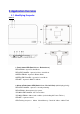
2. Application Overview 2.1. Identifying the parts: Case A 1. Panel Status LED (Dual Colour - Red & Green) RED LED ON - System in Arm Mode. RED LED FLASHES - System in Home 1/2/3 Mode. GREEN LED ON - System in Disarm Mode. GREEN LED FLASHES - System in Learn Mode. LED OFF - System in Walk Test Mode 2. Alarm & Fault Status LED (Dual Colour - Red & Yellow) (with display priority) RED LED FLASHES - System is currently alarming. RED LED ON - Alarm memory in system. YELLOW LED FLASHES - AC Power failure.
3. Operational Status LED (Dual Colour - Yellow & Red) (with display priority) YELLOW LED ON - Network error LED OFF – Network ok LED Flashing Sequence: Network ok >Network error 4. Buzzer 5. Ethernet Port 6. Learn / Reset Button 7. Empty Port 8. DC Jack For connecting the DC 12V, 1A switching power. 9. Battery Switch 10. Tamper Switch 11. Wall Mounting Bracket Case B 1. Panel Status LED (Dual Colour - Red & Green) RED LED ON - System in Arm Mode. RED LED FLASHES - System in Home 1/2/3 Mode.
YELLOW LED ON – Other fault condition (not including AC Power Failure ). LED OFF – System normal. : LED Flashing Sequence Alarm >Alarm Memory>Panel AC failure>Other Fault 3. Operational Status LED (Dual Colour - Yellow & Red) (with display priority) YELLOW LED ON - Network error LED OFF – Network ok LED Flashing Sequence: Network ok >Network error 4. Standing Base 5. Internal Buzzer 6. Ethernet Port 7. Learn/Reset Button 8. Base 9. DC Jack For connecting the DC 12V, 1A switching power. 10.
2.3. System Requirements: The system requires a TCP/IP network environment for MZ-1/8 IP Panel to be included in your network. To install the CD Wizard, your computer must have: Microsoft Windows 98, ME, NT4.0, 2000, XP, Vista, 7 or 8 operating system. Microsoft Internet Explorer 5.x, or later and Mozilla Firefox 1.0 compatible.
3. Getting Started Read this section of the manual to learn how to set up your MZ-1/8 Panel and program System Settings over the Web page. 3.1. Hardware Installation for MZ-1/8 Step 1. Connect the Power Adaptor to a Wall Outlet and the other end to MZ-1/8. MZ-1/8 will emit one short beep and Panel Status GREEN LED will turn ON. Step 2. Connect the Ethernet cable as described below: Step 2A: Plug-in the ethernet cable into the Internet jack on the Control Panel.
Step 6. Click “Next” to begin the Installation. Once the installation is completed, click “Finish” to confirm. Step 7. A new icon will be displayed on your desktop. Step 8. Double click on the “Finder.exe” to start the installation. The following screen will be displayed: Step 9. Click on “Search”, It will start searching for recognized IP address within the Local Network Service. Step 10. You will be able to locate the current MZ-1/8 IP address among the list.
2. CONFIGURE SETTING The Configure setting is for you to setup the network setting manually. Step 1. Click on Configure Setting, the following window will display: Step 2. Enter the network information and MZ-1/8’s web user name and password. (Default) User Name: admin (Default) Password: admin1234 Step 3. Click on OK to confirm.
4. Connecting to Webpage Step 1. Select MZ-1/8 in the Finder software and click on “Open Webpage” to connect to MZ-1/8 webpage. Alternatively, enter MZ-1/8 IP address displayed in Finder into your browser’s address section and click “GO”. Step 2. Enter the User name & Password. Step 3. Enter the User name & Password and then press “OK”.
Step 4. You will enter the Control Panel webpage, the current Control Panel information will be displayed.
5. SYSTEM SETTINGS 5.1. User User Code The User Codes are used for users to acess the alarm system. A total of 10 4-digit User Codes can be stored in MZ-1/8. Each individual User can be given a name for easy recognition when viewing system events. User PIN code #1 is activated with “1234” as factory default.
Temporary Code The Temporary Code is used to access the system for a temporary user and is valid only once per arming and once per disarming. Afterwards, the Temporary Code is automatically erased and needs to be reset for a new Temporary user. The Temporary Code consists of 4 digits and is not activated as default by the factory. Duress Code The Duress Code is used to access the system in duress situation.
5.2. Report This page is for you to enter the report destination setting. MZ-1/8 can store up to 8 report destinations. Reporting Type: MZ-1/8 supports 5 reporting types: IP/RF reporting in CID format: Reporting destination format: ip://Account@Server IP:Port/CID For Example: ip://6543@59.124.123.22:8765/CID ip:// 6543 @59.124.123.
IP/RF reporting in CSV format with user name and password: Reporting destination format: ip://Account@Server IP:Port/CSV/User/Password For Example: ip://6543@59.124.123.22:8765/CSV/ABCD/1234 ip:// 6543 @59.124.123.
Groups: You can assign reporting destinations to different groups, the reporting groups function according to the following rules: The reporting priority is based on to group number sequence. From Group 1 Group Group 2 Group 3 ….etc When more than one reporting destinations are assigned to a group, if a report is sent to one of the detinations successfully, the system will stop reporting to the rest of the reporting destination in the same group and move on to report to the next group.
5.3. Panel This page is for you to configure panel settings. Keyword The Keyword is used for receiving commands from users. When a user sends a command to the Control Panel, the correct keyword must be entered along with a valid User PIN code for the Control Panel to recognize the command. The Keyword is disabled by default. (MZ-8 only) P-word The P-word is also used for receiving commands from Installers.
Interval: Set the interval waiting time Offset Period: This is to set the time delay before the first “Auto Check-in Report” report to be made. For example, if “Offset” time period is set to 2 Hours, then the Control Panel will make the first “Auto Check-in Report” report after 2 hours, High Temp. This is for you to set the High Temperature reporting threshold.
5.4. Area This page is for you to configure area settings. Final Door Final Door On: When the system is Away Armed with a Door Contact set to Entry attribute, the system will automatically arm the system once the Door Contact is closed even if the entry delay timer has not expired yet. Final Door Off: When the system is Away Armed with a Door Contact set to Entry attribute, the system will only arm the system after the entry delay timer expires.
Factory default is set to 10 seconds. Exit Delay Set the Exit Delay Timer for Away Arm, Home Arm 1, Home Arm 2, and Home Arm 3 modes. When you arm the system, the system will enter your selected arm mode after the Exit Delay Timer expires Factory default is set to 10 seconds. Alarm Length When an alarm is activated, both the Control Panel siren and external siren will raise alarm according to the Alarm Length setting. Factory default is set to 3 minutes.
5.5. Network This page is for you to configure network settings. DHCP On: If DHCP is set to On, the Network will obtain the IP address automatically with a valid Network DHCP Server. Therefore, you won’t need to do any settings. You can only set DHCP to On if your Network environment supports DHCP. It will automatically generate all information. Off: If DHCP is set to Off, you neet to enter the Network information manually for IP Address, Subnet mask, Default gateway, Default DNS.
SMTP setting must be entered in all lowercase letters MZ-1/3/8 does not support SMTP encryption method such as SSL or TLS. Administrator Account Setting Here you can program the user name and password used for accessing the webpage. Web User: This is the user name you entered when you access the panel webpage. Default web user is “admin”. If you want to change the user name, enter a new name in the field. Maximum character allowed is 20.
5.6. Upload This page is for you to set upload destination for captured pictures and videos from PIR Camera and PIR Video Camera. 1~5 Enter an email address, FTP address, server address, or mobile number for MMS delivery For email delivery, the SMTP setting under Network must be completed. The format is: mailto: user@example.com For MMS delivery to mobile phone (MZ-8 only), the MMS setting under RF must be completed. The format is: mms: 0987654321 For FTP, the format is: ftp://user.password@example.
6. Device Management This page for you to learn in, edit, delete and control all the accessory devices. A total of 40 devices are allowed to be learnt in to the system, including RF and ZigBee devices. Only 6 PIR Cameras (VST-852/VST-852 Pro) or Video Camera (VST-873/VST-873Pro) can be learnt into the system. 6.1. Learning Step1. Under Disarm Mode, press “Start Learning”. The Control Panel will enter learning webpage. The Control Panel LED 1 will flash green. Step2.
device information when you refresh the page, it means the Control Panel received supervision code from the sensor instead of learn code. Please resend the learn code again. Step4. Tick the device # box, then click “Add” to include the device in the Control Panel. Step5. The Control Panel will display “Updated Successfully” message and the new learned in device zone accordingly. The device is now learn in to the system. Step6.
Step7. After learning a device into the Control Panel, the Device Webpage will be changed to list all available functions. Local Learning: The Control Panel feature local learning function for you to learn in the device without using the webpage Step1. Press and hold the learning button on the back of Control Panel for 10 seconds and release when you hear a beep. The LED 1 will begin to flash green to indicate the Control Panel is in learning mode. Step2.
6.2. Add Device For RF devices, you can also add device into the Control Panel by entering the device’s RF code. (This function cannot be used with ZigBee devices) Step1. Select the zone number you want to assign the new device to Step2. Enter the device’s RF code Step3. Enter device name. Step4. Click “Add RF Device ” to include the device in the system.
6.3. Walk Test Step1. Press “Start Walk Test” under either Learning or Device Management webpage. The Control Panel will enter Walk Test page. Step2. Press the learn button on your device (please refer to device manual for detail) to transmit a test code. Step3. If the Control Panel receives the test code, it will emit a long beep, click the “Refresh” button to displayed accordingly on the webpage. Step4. You can click “Stop” button to terminate walk test, the Control Panel will return to normal mode.
6.4. Edit Device After you learn in a device to the system, you should proceed to edit its setting. Step1. Under Device Management webpage, click “Edit”. The Control Panel will enter device editing page. Step2. Proceed to edit device settings, click “Submit” when you are satisfied with all settings or information..
Name: Enter a name for the device, A maximum of 20 characters are allowed Zone: Select the device zone number. Attribute: For Door Contact you are requested to select the device attribute from Burglar, Home Omit, Home 1/2 Omit, Home 1/3 Omit, Home Access, Delay Zone, Away Only, Entry, Away Entry, 24 Hr, Fire, Medical Emergency, Water, Set/Unset Silent Panic, Personal Attack.
When the system is in any Armed mode, and the Control Panel is counting down the Entry Delay, if a “Burglar” device is triggered, the Control Panel will not respond. During the Exit Delay period, if a “Burglar” device is triggered, the Control Panel will not respond . Away Only When the system is in Away Arm mode, if an “Away Only” device is triggered, a “Burglar Alarm” will be activated immediately and reported.
Water The Water device is active all the time and does not have to be armed or disarmed. An Event Code of #154 will be reported with trigger. Set/Unset (For Door Contact Only) If the Door Contact is set to Set/Unset, the system will be disarmed when the Door Contract is triggered, and armed when Door Contact is closed. Please refer to Normal Open/Normal Close section below for further detail.
6.7. Power Switch Control This section is for you to control Power Switch in the system Switch On: Select the desired Power Switch, then choose the time length you want to turn on the Power Switch, then click “Switch On” to confirm. Switch Off: Select the desired Power Switch, then click “Switch Off” to turn off. Switch Toggle: Select the desired Power Switch, the click “Switch Toggle.” If the Power Switch is on, it will be turned off; if the Power Switch is off, it will be turned on instead.
7. Captured Events Pictures/Videos captured by PIR Camera and PIR Video Cameras will be displayed in this page. Only the pictures/videos of the 6 latest events will be stored. Click on the image or video to view the file. Time: The time when the picture/video is captured. Device: The Zone number of the PIR Camera/Video Camera triggered. Type: The type of the image/video. Alarm Image: When triggered under Away Arm/Home Arm mode, the PIR Camera will take three pictures.
Waiting for Capture: The PIR Camera/Video Camera is sending captured picture/video the the Control Panel. For Alarm Image/Video, if you disarm the Control Panel under this status, the captured image/video will be deleted and no image/picture will be sent. Upload: The PIR Camera/Video Camera has finished sending image/picture to Control Panel. The Control Panel is now uploading the image/video to programmed destination.
8. History Records 8.1. History The Control Panel history events are recorded in this page. The History memorizes the last 50 Panel events including: All Alarm Events with Device Zone All Fault Warning Events from Panel or Device All Arming And Disarming Events by Panel and Remote Controller All Arming and Disarming Events by Remote Keypad with User information.
8.2. Reported Event The reported event history are recorded in this page.. A total of 50 reported events can be recorded with Time, CID Event Code, Device Group/Zone and User information. Time: The time when the Control Panel begins the report CID Event Code Format: The CID event code is recorded in 4 digits format of “Prefix + Event Code” Prefix: “1” represents events taking place. “3” represents event restore. Event Code: 3-digit CID event code.
9. Panel Control Under this page, you can choose to Away Arm, Home Arm 1/2/3, or Disarm the system. If any fault exists within the system, they will be displayed under this page. Current Mode Control Panel current mode. Away Arm: Away Arm will arm all devices in the system. Home Arm 1/2/3: You can choose to arm the system in 3 different Home Arm mode. Under Home Arm 1, device set to Home Omit, Home 1/2 Omit or Home 1/3 Omit will not raise an alarm when triggered.
10. Home Automation This page is for you to setup Home Automation rules with condition and execution setting to control the alarm system or home appliance automatically. A total of 20 Home Automation rules are available for setting. Step1. Click “Edit” to configure setting for the selected rule number. You will enter edit page. Step2. Set the Rule Condition. Mode Changed: The rule will be activated when the system mode is change to set mode.
Greater Temp: The rule will be activated when the temperature rises above set value. Lower Temp: The rule will be activated when the temperature drops below set value. Timer: The rule will be activated when system reaches set time Step3. Set the Execution Rule Switch Group: All Power Switches in selected group will be turned On/Off for set duration according to your setting. Switch Zone: All Power Switches in selected zone will be turned On/Off for set duration according to your setting.
Home Omit No Response Home1/2 Omit No Response Home1/3 Omit No Response Home Access No Response Away Only No Response Instant Burglar Alarm Instant Burglar Alarm Instant Burglar Alarm Instant Burglar Alarm Instant Burglar Alarm Start Entry Timer Door Chime Entry (DC & IR Only) Door Chime Start Entry Away Entry (DC & IR Timer Only) Instant Instant Burglar 24 HR Alarm Burglar Alarm Instant Delay Zone No Response Burglar Alarm Instant Fire Instant Fire Fire Alarm Alarm Instant Instant Medical/Emerge
Silent Panic Personal Attack Instant Instant Instant Instant Instant Instant Instant Instant Silent Silent Panic Silent Panic Silent Panic Silent Panic Silent Panic Silent Panic Silent Panic Panic Alarm Alarm Alarm Alarm Alarm Alarm Alarm Alarm Instant Panic Instant Instant Instant Instant Instant Instant Instant Panic Alarm Alarm Panic Alarm Panic Alarm Panic Alarm Panic Alarm Panic Alarm Panic Alarm Press “Save”. A message edit screen will appear for you to confirm.
14. Event Code The events are reported with a qualifier before the event code. The qualifier “1” means the event has taken place, “3” means the event has been restored. For example, if the Control Panel reports “1302”, it means the panel is under low battery; if the Control Panel reports “3302”. It means the panel low battery condition has been restored. 100 – Medical 101 – Personal emergency When the Wrist Transmitter / Emergency Pendant (WTR) is pressed.
158 – High Temperature When the temperature exceeds High Temperature setting. 159 – Low Temperature When the temperature drops below Low Temperature setting. 162 – CO detector 301 – AC Failure When the AC power fails for more than 10 sec. 302 – Low Battery When the Control Panel is under low battery. 311 – Panel Battery Missing/Dead When the Control Panel Battery is missing or disconnected.