
Installation Instructions

2
3) To receive the new sensitivity level and mode data from the Panel straightaway, press the Test button of SVGS-5
once. The LED indicator will brighten and dim within two 2 seconds to indicate successful operation. Otherwise,
SVGS-5 will receive sensitivity level and mode change data automatically when next time it is transmitting signal
(e.g. supervision or alarm trigger).
Test Mode
The Sensor can be put into 3 minutes Test Mode by pressing the test button:
Press the Learn/Test button once, the LED will flash to indicate the Sensor is put into Test Mode.
Under Test Mode, every time when the Sensor is triggered, the LED will flash.
The Sensor will exit Test Mode after 3 minutes.
Sleep Timer
The Sensor will enter a sleep time of 2 minutes after each trigger. The sensor will not retransmit detection signal during
this 2-minute period. Each shock detection trigger during this period will rest the sleep timer back to 2 minutes. The sleep
time will only expire if no shock is detected for 2 minutes, then the Sensor will return to normal operation and transmit the
next shock detection signal.
Learning and Installation
Learning
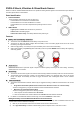
1. Pull out the battery insulator power on the sensor.
2. Refer to Control Panel manual to put panel into learning mode.
3. Press the Learn/Test button once to transmit a learn code.
4. Refer to your Control Panel operation manual to complete the learn-in process.
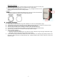
Mounting Surface and Material
The Sensor should be mounted direct on glass or plywood surface.
Glass thickness: Plated, tempered and laminated glass: Minimum 5 mm.
Plywood thickness: Maximum 9mm.
Safety Box thickness: Minimum 3mm
Sensitivity and Detection Range
The Sensor sensitivity is adjusted via Control Panel. The detection range of different sensitivity varies depending on the
mounting surface materials.
Glass Plywood Safety Box
Material
Plated/Tempered/Laminated
/Wired Glass
Plywood Steel / Silicon Dioxide
Thickness Minimum 5mm Maximum 9mm Minimum 3mm
Shock/Vibration
Detection Mode
Single Pulse Mode
Multi Pulse /Accumulated
Vibration Mode
Sensitivity
Low 8000mm 2000mm -
Medium 10000mm 2500mm -
High 12000mm 3000mm 1400mm
Installation Steps and Guideline
1. Adjust the sensor’s sensitivity as desired according to mounting surface material using table supplied in previous
section.
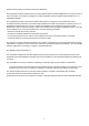
Window/Wall Installation:
Determine the mounting location on window or wall. The sensor may be mounted at the center or at the corner. If one
sensor is unable to cover the entire surface, use multiple sensors.
<NOTE>
When mounting at corner, make sure to keep at least 10mm distance between the sensor and the edge of window or
wall. Adjust the battery slot direction (Do not face the corner) to avoid difficulty when removing the battery slot.