Public View CE-20DVRPVM-HD & CE-8DVRPVM-HD User Manual CLINTON Electronics 6701 Clinton Road Loves Park, IL 61111 POWER AUTO 1.800.447.3306 Sales 1.800.549.6396 Support 1.800.633.8712 Fax UP DOWN www.clintonelectronics.com MENU v.02.16.
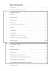
Table of Contents Introduction . . . . . . . . . . . . . . . . . . . . . . . . . . . . . . . . . . . . . . . . . . . . . . . . . . . . . . . . . . . . . . . . . . . 3 Display Contents, Installation and Set-up . . . . . . . . . . . . . . . . . . . . . . . . . . . . . . . . . . . . . . . . . . . . . . . 4 Adjusting the Display. . . . . . . . . . . . . . . . . . . . . . . . . . . . . . . . . . . . . . . . . . . . . . . . . . . . . . . . . . . 5 Feature List . . . . . . . . . . . . . . . . . . . . . . . . . .
Introduction Congratulations on the purchase of your new Public View Integrated Camera Security display. This display and camera combination is designed for simple and effective loss prevention by making the viewer aware of video surveillance measures. The BNC output allows the video to be recorded on a DVR or VCR device.
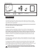
PACKAGE CONTENTS POWER POWER UP AUTO DOWN MENU POWER AUTO UP DOWN AUTO UP DOWN MENU MENU 2 GB SD Card 2 16 GB SD Card AUTO UP DOWN 2 GB SD Card 2 SDHC Cards • DVR (16GB) • Video (2GB) CE-DVRPVM POWER GB SD Card MENU 16 16 GB SD Card GB SD Card Remote Controls • DVR • Display Power Pigtail (for Hardwiring) User Manual Installation and Set up Unpacking your display 2 GB 16 GB Your Public View display comes with the remote control and power connector.
Adjusting the Display The display comes from the factory in a pre-set configuration that will be very close to the final set up for most installations. Minor adjustments can be made to the monitor and camera to optimize the picture quality for a particular installation when required. Adjusting the monitor The monitor can be adjusted by either the included remote control, or with the OSD (On Screen Display) buttons located at the rear of the monitor. These controls will adjust all parameters of the display.
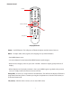
Features CE-20DVRPVM-HD Dwell Time Dial Sensor Switch Sensitivity Dial Audio Switch Camera PIR Sensor LED Flasher SD Card Inserted Light (behind glass) Video SD card slot OSD menu buttons DVR SD card slot Power Supply Input BNC Output OSD VGA Input Board Controls (bottom) CE-8DVRPVM-HD OSD menu buttons Power Indicator Light BNC Output Audio Switch Sensitivity Dial Sensor Switch Dwell Time Dial Power Supply Input IR Sensor SD Card Inserted Light Camera PIR Sensor LED Flasher Video SD card slot
Remote Control Power Selection Arrows Menu Sleep TV (source) Display Remote Power – On/Off function. This will power off both the display and the internal camera. Menu – To adjust audio, video, signal, tools, language use up & down buttons. • Push MENU button once. • Use arrow buttons located around the MENU button to pick category. • When correct category is chosen, press VOL- and VOL+ buttons to adjust given parameter of display.
Display Set-up Video Menu: The display should be pre-set for most installations, however if some adjustment is necessary, we suggest you follow these recommendations by pressing the MENU button on the Display remote: 1. First adjust the BRIGHTNESS control to set the black level so that the images are at their brightest while the black images are still black. Do not adjust too high where the black portions of the image become gray or the image will have a “washed out” appearance. 2.
Audio Menu 1. The Audio Menu will not be used on this unit. It has no impact on the volume of the motion chime that is set on the back of the unit. The MUTE function on the remote also has no impact on the motion chime. Feature Controls Menu 1. The SLEEP TIMER is adjustable from 0min to 90min. After which time, the display will time out until motion 2. The LANGUAGE can be changed to one of the following: English, French, German, Spanish, Italian, Dutch, Greek, Swedish. 3.
ide for CE-20DVRPVM-HD & CE-8DVRPVM-HD PIR SENSOR CONTROLS PSZ UP SFDPSE PO NPUJPO 5IFTF TFUUJOHT IBWF CFFO QSF MPBEFE BOE TIPVME OPU CF DIBOHFE PIR Sensor Controls UJOH UIF 4% DBSE TFUUJOH UIF MPDBM UJNF BOE JG EBZMJHIU TBWJOHT UJNF %45 JT SFDPHOJ[FE JO ZPVS BSFB 5IF 1*3 TFOTPS QJOIPMF MPDBUFE GSPOU DFOUFS PO VOJU DPOUSPMT UIF TDSFFO TXJUDIJOH PG UIF øBTI DBSE QMBZFS UP UIF CVJMU JO DBNFSB *U BMTP DPOUSPMT UIF BVEJP #F TVSF UP LFFQ UIF TNBMM IPMF PQFO BU BMM UJNFT BOE GSFF PG EVTU *U EPF
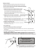
Access to the Camera and OSD Board A. CE-20DVRPVM-HD The access door to the camera and OSD Board is located at the bottom of the 20” unit, and back of the 8” unit. A Phillips screwdriver is required to remove the access panel screw from the 20’ unit (Fig. A), place the screw in a location where it will not be lost. The access panel for the 8” unit can be finger loosened (Fig A2).
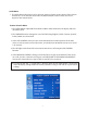
Settings Settings can be made using the 5 button OSD Board located on the under side of the door. UP LEFT RIGHT SET DOWN 1. Press the SET button to activate On-Screen SETUP Menu 2. Select the function you wish to adjust using the UP or DOWN button. 3. When the LEFT or RIGHT button is pressed, the available modes are displayed (*Note: Some menu selections may not have multiple modes to select). Keep pressing the button until you get the mode you wish to operate. 4.
Lens (selection) 1. When the SETUP menu is displayed on the screen, position the arrow to point to LENS by using the UP or DOWN button. 2. You may select the type of lens you wish to use by pressing the LEFT or RIGHT button. DC: Auto iris lens selection• The optimum level of brightness can be adjusted within the range of 1 ~ 70. MANUAL: Manual lens selection• If MANUAL mode is selected, the brightness can be adjusted in ESC mode. 3. Press the SET button to return to previous menu.
White Balance The screen color can be adjusted by using the WHITE BALANCE function. 1. Position arrow to point to WHITE BAL. using UP or DOWN button. 2. Select the mode you wish to operate by pressing the LEFT or RIGHT ATW (Auto Tracking White Balance): This mode can be used within the color temperature range 1,800ºK ~ 10,500ºK (eg.
BLC (Backlight Compensation) When there is a strong backlight behind the object, clear images of the background as well as the object can still be obtained by using the BACKLIGHT function. 1. Position the arrow to point to BACKLIGHT on the SETUP menu by using the UP or DOWN button. 2. Select the mode you wish to operate by pressing the LEFT or RIGHT button.
DNR (Digital Noise Reduction) The background noise in the low light level decreases automatically as the level of gain changes. 1. Position the arrow to point to DNR on the SETUP menu by using the UP or DOWN button. 2. Select the mode you wish to operate by pressing the LEFT or RIGHT button. OFF: There is no reduction in noise level. LOW: There is a small reduction in noise level with almost no ghost image. MIDDLE: The most effective mode.
Special 1. Position the arrow to point to SPECIAL on the SETUP menu by using the UP or DOWN button. 2. Enter the SPECIAL options menu by pressing the SETUP button. CAMERA ID: Use this function to input the camera’s ID/name and have it appear on the monitor. 1. Position the arrow to point to CAMERA ID by using the UP or DOWN button. 2. Select ON by pressing the LEFT or RIGHT button. 3. Press the SET button to enter the ID menu.
5. Move the cursor to “POS” and press the SET button. You will now see a preview of how the ID/name will appear on the screen. 6. Press LEFT, RIGHT, UP, or DOWN to position the ID/name in the desired position on the screen. 7. Press SET to lock the ID/name in place, and return to the previous CAMERA ID screen. 8. Navigate the cursor to END, and press SET to exit.
COLOR: - AUTO: This camera has a function which automatically changes to the appropriate mode for daytime or night-time. The camera is in COLOR mode for daytime, and automatically switches to BW mode for night-time. -ON: The color mode is selected by default, and the modes do not change automatically. • When AGC is turned off, COLOR does not operate. • When an infrared light is used, there may be a problem with focusing. SYNC: Two Synchronization modes are available: INTERNAL, and EXTERNAL LINE-LOCK.
PRIVACY: This mode conceals up to 4 areas you wish to be private during viewing, and recording playback. - OFF: Disables PRIVACY mode - ON: Activates PRIVACY mode Press SET button to enter parameters. • Select the area you wish to have private from the 4 areas in AREA SEL.
DVR Controls / Settings Record Return/Stop DVR Remote Control Play/Pause – Press once to play, press again to pause playback. Return/Stop – Press to Stop playback. Also used to return to previous screen. Play/Pause Selection Arrows Selection Arrows –Use to navigate through menus. Also used to Fast Forward or Fast Reverse in playback mode. Menu/OK Menu/OK –Brings up menu, and selects menu items. Record –Not used (recording begins automatically when unit is on).
Playback view To start playback you can decide between three different modes. Normal playback During live view press the playback/pause button to start normal playback. Normal playback speed. During the normal playback press or button to rewind or fast forward. By pressing in the same direction again you raise the search speed (Speed: x2/ x4/ x8/ x16/ x32). Press button to playback at normal speed. During playback, press button to pause playback and press again to return to playback status.
Main Menu 1 The menu level is shown in the top right corner of the menu screen. First level (main menu) Second level Third level - Press or buttons to navigate. - To confirm or select, press button. - Press or buttons to change the value. - Press button to exit the menu. Date / time setup Date Format Here you can change the way the date is displayed. Date/ Time Adjustment Here you can change the date and time.
Motion setup SET MD AREA The motion detection area is split up into 16 x 12 cells. Cells which are marked to detect motion are displayed red. In order to navigate use buttons and confirm by pressing playback button in order to change the editing mode. button. Press Editing modes: CELL EDIT Here you can (de-) activate every single cell. DEL BLOCK Here you can deactivate a complete block of cells. DEL ALL Here you can deactivate all cells at once.
Manual record - VIDEO SIZE / FRAME RATE: Here you can change the video size and frame rate for the manual recording. Video size 320 x 240 640 x 480 Max. frame rate 30 fps 12 fps - QUALITY: Here you can choose between three recording qualities: High, Medium, Low Schedule record Here you can see a short a summary of the settings for motion and continuous recording. SCHEDULE SETUP Activate / Deactivate the schedule and the recording settings. MOTION RECORD Settings for the motion detection.
Schedule setup SCHEDULE Recording ON / OFF (default value is OFF) 00 - 23 Use to navigate between the hours. Press or to change the recording types. ( : Motion; : Continuous; Alarm; _: All modes active; : No mode active) Alarm record Here you can change the settings for the alarm recording. ALARM RECORD ALARM INPUT : N.C. VIDEO SIZE Here you can set the recording resolution. FRAME RATE Here you can set up how many fps shall be recorded. QUALITY Here you can set the recording quality.
Continue record Here you can change the settings for the continuous recording. VIDEO SIZE Here you can set the recording resolution FRAME RATE Here you can set up how many fps shall be recorded. QUALITY Here you can set the recording quality. SD-Card Options DISK TOTAL Shows the total capacity of the inserted SD-Card. DISK REMAIN Shows the remaining capacity of the inserted SD-Card. MAX FILE SIZE Here you can set the max. file size (3 – 100 MB) of a recording.
System Status Here you can find a quick summary of the firmware version and the recording settings. Press any key to return to the main menu. Power on Setup LANGUAGE Here you can set the OSD menu language. COMPOSITE Here the video standard for the video output is shown. Factory Default Here you can reset all settings, except Date and time, to factory default. Press Press button to reset to factory default. button to cancel factory default and return to the main menu.
Troubleshooting: Your Public View Monitor has been designed for years of trouble-free operation. However, if you do encounter an issue, please follow the recommended troubleshooting guide below. No Image on Screen 1. Press the POWER button on the rear of the display or on your remote control. If the fan turns on and a NO SIGNAL message appears, you must change the input setting.
v.01.25.