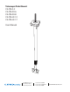
Telescopic Pole Mount CE-CM-S-2 CE-CM-SX-6 CE-CM-SX-8 CE-CM-LX-12 CE-CM-LX-17 User Manual M4 Washer M4 x 45mm M4 Washer M4 Lock Nut 1/4”-20 x 2” 1/4”-20 Lock Nut 1/4” Lock Washer 1/4” Washer 1/4” Washer M4 x 8mm VESA screw (4 places) 1/2”-13 Lock Nut Fender Washer Truss or Channel Strut Min. Hole Size: 1/2” Max. Hole Size: 5/8” 10 7/16 Min. Steel Thickness: 1/4” Pole will move in the direction of the tightened bolt CLINTON Electronics 6701 Clinton Road Loves Park, IL 61111 1.800.447.
WARNING Prior to installation and use of this product, please observe the following warnings: 1. Installation and servicing should be done by qualified personnel, and all work done should conform to local codes. 2. Using replacement parts or accessories other than from the manufacturer may void the warranty. This symbol indicates that there are important operating and maintenance instructions in the literature accompanying this unit.
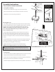
d. Assembly Instructions U-Bolt Cable Clamp 1/2”-13 Lock Nut If drilling is necessary, Use 9/16” metal drill bit to drill through steel mounting surface. Fender Washer Truss mount or channel strut mount Cord Management Hole Truss or Channel Strut Securing Mount to Building: 1. Insert threaded rod between truss gap or into hole in channel strut. Min. Hole Size: 1/2” Max. Hole Size: 5/8” 2. Place 1/2” fender washer over the threaded rod and then 1/2” lock nut. Min. Steel Thickness: 1/4” 3.
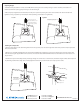
Adjusting Height: 1. Hold the lower pole (where it connects to the LCD) while loosening the center collar by turning it counter-clockwise (see illustration on U-Bolt Cable Clamp left below). Extend the pole by gently lowering it to the desired length. rd Management Hole 2. Once the proper length has been maintained, lock the pole in position by rotating the center collar clockwise. The collar should be hand tightened as snug as possible to prevent the pole from expanding.