Public View CE-M8SD-B User Manual CLINTON Electronics 6701 Clinton Road Loves Park, IL 61111 1.800.447.3306 Sales 1.800.549.6393 Support 1.800.633.8712 Fax www.clintonelectronics.
Table of Contents Display DVR Camera Introduction………………………………………………………………………… 3 Contents, Installation and Set-up…………………………………………………… 4 Display Functions…………………………………………………………………… 5 LCD Remote Control………………………………………………………………… 6 Display System Settings……………………………………………………………7-8 SD-Card Files………………………………………………………………………… 9 DVR Remote Control……………………………………………………………… 10 DVR Settings…………………………………………………………………………11 Playback…………………………………………………………………………… 12 Main menu, Date & Time……………………………………………………………13 Motion De
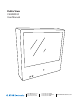
Introduction Congratulations on the purchase of your new Public View Integrated Camera Security display. This display and camera combination is designed for simple and effective loss prevention by making the viewer aware of video surveillance measures.
POWER PACKAGE CONTENTS UP AUTO MENU DOWN 2 GB SD Card 2 2 GB SD Card 2 16 GB SD Card GB SD Card 2 GB SD Card 16 GB SD Card 16 16 GB SD Card GB 2 16 16 GB SD Card GB SD Card GB SD Card SD Card GB SD Card 2 GB SD Card CE-M8SD-B with access door and security screw Security Allen Wrench Extra Security Screw 16 GB SD-Card (for DVR) 2 GB SD-Card (for media) Alarm SD-Audio Motion Chime 1 ON 2 3 4 Remote Control (batteries included) Power Pigtail (for Hardwiring)
Display Functions 2 GB SD Card 16 GB SD Card Features VESA 75 & VESA 100 mounting patterns Power Supply Input Video SD-card slot BNC Output Alarm Connection DVR SD-card slot Camera Camera OSD Joystick LED Flasher IR Sensor Control Access The access door for the OSD Joystick, SD-Cards, and Connections on the back of the unit WHEN is SDlocated CARD IS INSERTED, YOU MUST POWER CYCLE. and must be removed using the included security allen wrench.
Remote Control - LCD The parameters of the display can be adjusted by using the included remote control. LCD CONTROLS Power Mute Selection Arrows Menu DVR AV DVR CONTROLS REC (see page 10 for DVR controls) MENU OSD Exit SOURCE 912-F8125-0001 LCD CONTROLS Power – On/Off function. This will power off the display only. The internal camera can still supply video to an external display or DVR. Mute –Disables the audio on the unit. Menu – Adjustment of audio, video, signal, tools, & language.
Display Set-Up Video Menu: The display should be pre-set for most installations, however if some adjustment is necessary, we suggest you follow these recommendations by pressing the MENU button on the remote control: 1. First adjust the BRIGHTNESS control to set the black level so that the images are at their brightest while the black images are still black. Do not adjust too high where the black portions of the image become gray or the image will have a “washed out” appearance. 2.
System Settings Menu 1. The ALARM CAMERA DWELL will allow you to change the duration that the camera image will remain on screen after an alarm event has occurred. If you wish to change this duration for motion events, you must do so in the DVR Settings menu. See pg. 16 for details. 2. The LANGUAGE can be changed to one of the following: English, French, German, Spanish, Italian, Dutch, Greek, Swedish. 3. In OSD CONTROL you can control the following: 3a.
SD Card SD Card Change SD-Card Image/Video/Audio • Insert the SD-Card into your computer or SD-Card reader. • Move the desired JPEG image, or AVI video file into the SD-Card folder. (For the M8SD-B the desired full screen image size is 800x600) • Leaving multiple media files on the SD-Card will result in the device cycling through all loaded media. • Insert the SD-Card back into the PVM with the contacts facing out, as shown on the rightDO NOT FORCE IT IN.
Remote Control -DVR The parameters of the display can be adjusted by using the included remote control. LCD CONTROLS (see page 6 for LCD controls) DVR AV DVR CONTROLS REC Play / Pause OSD Exit Exit / Stop Down Record MENU Back / Rewind Up Forward / Fast Forward OSD Controls SOURCE 912-F8125-0001 Menu / OK Source DVR CONTROLS Play / Pause –Press once to play, press again to pause playback. Menu/OK – Use to open Menu and to select functions.
DVR Settings Recording View 2011 2 1 3 4 5 6 720 480 7 8 9 HQ Select from: Yr / Mo / Day or Mo / Day / Yr, 1 Current Date & Time 2 Record Status Device is Recording Data 3 Record Mode Manual Record 4 Video Size HOUR : MINUTE : SECOND Schedule Record 360 Quarter VGA Quality 240 360 x 240 720 480 Motion Record VGA Quality 720 x 480 5 Recording Quality BQ Basic Quality NQ 6 Audio Status No Audio recording supported with this device (Disregard Audio Symbol) Normal Quality HQ High
Playback view To start playback you can decide between three different modes. DVR Normal playback During live view press the playback/pause DVR AV REC button to start normal playback. DVR AV AV MENU Normal playback speed. Exit REC REC OSD DVR AV During the normal playback press or button to rewind or fast forward. By pressing in the REC same direction again you raise the search speed (Speed: x2/ x4/ x8/ x16/ x32). Press button to DVR AV playback at normal speed.
Main Menu 1 The menu level is shown in the top right corner of the menu screen. First level (main menu) Second level DVR AV Third level DVR DVR MENU AV DVR REC AV DVR AV AV - Press or buttons to navigate. REC - To confirm or select, press button. MENU - Press or buttons to change the value. - Press Exit buttonOSD to exit the menu.
Motion setup SET MD AREA DVR AV The motion detection area is split up into 16 x 12 cells. Cells which are marked to detect motion are displayed red. DVR DVR DVR AV AV DVR REC REC MENU REC MENU OSD Exit OSD MENU Exit Exit MENU OSD OSD Exit REC MENU button. Press play- OSD Exit AV CELL EDIT Here you can (de-) activate every single cell. DEL BLOCK Here you can deactivate a complete block of cells. DEL ALL Here you can deactivate all cells at once.
Manual record AUDIO : OFF - VIDEO SIZE / FRAME RATE: Here you can change the video size and frame rate for the manual recording. Video size 360 x 240 720 x 480 Max. frame rate 30 fps 30 fps - QUALITY: Here you can choose between three recording qualities: Basic, Normal, High - AUDIO: This feature is non functioning on this device. Schedule record Here you can see a short a summary of the settings for motion and continuous recording.
DVR AV Schedule setup REC SCHEDULE Recording ON / OFF (default value is OFF) DVR DVR AV AV MENU Use to navigate between the hours. Press or to change the recording types. ( : Motion; : Continuous; Alarm; _: All modes active; : No mode active) Exit OSD 00 - 23 Exit MENU Exit MENU REC OSD REC MENU OSD Exit OSD DVR REC AV Event record Here you can change the settings for the motion detection.
Continue record Here you can change the settings for the continuous recording. AUDIO VIDEO SIZE : OFF Here you can set the recording resolution FRAME RATE Here you can set up how many fps will be recorded. QUALITY Here you can set the recording quality. AUDIO Audio recording is not available on this device. Disregard this menu item. SD-Card Options DISK TOTAL Shows the total capacity of the inserted SD-Card. DISK REMAIN Shows the remaining capacity of the inserted SD-Card.
System Status Here you can find a quick summary of the firmware version and the recording settings. Press any key to return to the main menu. Power on Setup ALARM INPUT : N.C. LANGUAGE Here you can set the OSD menu language. COMPOSITE Here the video standard for the video output is shown. ALARM INPUT Here the alarm input can be set. (normally closed; normally open) Factory Default DVR AV Here you can reset all settings, except Date and Time, to factory default.
Camera OSD Menu Camera functions and settings can be adjusted or changed by activating the OSD menu. When the OSD menu is activated text will display on the monitor. The user can then move the cursor to the desired function to change the setting.
Navigating the OSD Menu 1. Press the SETUP button, then select a menu item from the list available by using the UP and DOWN buttons. • Functions are selected using up and down buttons. • Place the cursor over a desired item, the selected position is displayed. Select the function using the UP or DOWN button. When an arrow is present, press SETUP button to enter sub-menu Change the status using the LEFT or RIGHT button. 2. Set up a selected item by using the Left and Right buttons. 3.
Exposure 1. When the SETUP menu is displayed, select ‘EXPOSURE’ by using the Up and Down buttons so that the arrow indicates ‘EXPOSURE’. Press SETUP to enter. 2. Select the desired mode using Up and Down buttons. BRIGHTNESS: Adjusts the exposure brightness. SHUTTER: You can select either auto or manual shutter. – A.FLK : Select this when you experience picture flicker, which can happen when there is a clash with the frequency of the installed lighting.
Exposure- continued Notes • If you press the SET button in ‘AUTO’ mode, you can adjust brightness by increasing or decreasing the shutter speed. (x2 ~ x512) • Note that the higher the zoom level, the brighter the screen, but the more likely it is that an afterimage will appear. • Although noise, spots, and whitish symptoms may occur in SENS-UP operation when the zoom level is increased, this is normal. White Balance Control Use the White Balance function to adjust the screen color. 1.
SSDR (Super Dynamic Range) SSDR illuminates darker areas of an image while retaining the same light level for brighter areas to even out the overall brightness of images with high contrast between bright and dark areas. 1. When the SETUP menu screen is displayed, select ‘SSDR’ by using the Up and Down buttons so that the arrow indicates ‘SSDR’. 2.
BLC (Back Light Compensation) 1. When the SETUP menu screen is displayed, select ‘BACKLIGHT’ by using the Up and Down buttons so that the arrow indicates ‘BACKLIGHT’. 2. Select a desired mode using the Left and Right buttons depending on the camera purpose. BLC: Enables a user to select a desired area on a picture and view that area more clearly.
HLC continued 3. Select a desired mode using the Left and Right buttons and press the SET button. BLC : Select ‘BLC’ to adjust the area to be enhanced then adjust the level. HLC :Enable the user to change the level limit, mask color/tone and area. Notes • For effective license plate observation, it needs minimum illumination and fast shutter speed more than 1/200sec.
DNR3 This function reduces the background noise in a low luminance environment. 1. When the SETUP menu screen is displayed, select ‘DNR’ by using the Up and Down buttons so that the arrow indicates ‘DNR’. 2. Select a desired mode using the Left and Right buttons. OFF: Deactivates DNR. Noise is not reduced. ON : Activates DNR so that noise is reduced. 3. Set the DNR mode to ‘ON’ and press the SET button. Then you can adjust the noise reduction level.
Day / Night You can display pictures in color or black and white. 1. When the SETUP menu screen is displayed, select ‘DAY/NIGHT’ by using the Up and Down buttons so that the arrow indicates ‘DAY/NIGHT’. 2. Select a desired mode using the Left and Right buttons according to the picture display you want. EXTERN : This mode allows you to apply a desired filter to external signals. COLOR : The picture is always displayed in color.
SPECIAL 1. When the SETUP menu screen is displayed, select ‘SPECIAL’ by using the Up and Down buttons so that the arrow indicates ‘SPECIAL’. Press SETUP to enter the ‘SPECIAL’ menu. 2. Select a desired mode using the Up and Down buttons. IMAGE ADJ: 1) When the SETUP menu screen is displayed, select ‘IMAGE ADJ.’ by using the Up and Down buttons so that the arrow indicates ‘IMAGE ADJ.’ Press SETUP to enter ‘IMAGE ADJ’. 2) Select a desired mode using the Up and Down buttons.
Image Adj. Continued l FONT COLOR : You can change the OSD font color. (White, Yellow, Green, Red, Blue) l SHARPNESS : As you increase this value, the picture outline becomes stronger and clearer. Adjust this value appropriately depending on the sharpness of the picture. l RETURN : Select this to save the settings for the IMAGE ADJ. menu and to return to the SETUP menu. Notes • When the V-REV or H-REV mode is enabled, the text on the screen does not flip.
CAM TITLE : If you enter a title, the title will appear on the monitor. 1) If the SPECIAL menu screen is displayed, use the Up and Down buttons so that the arrow indicates ‘CAM TITLE’. 2) Set it to ‘ON’ by using the Left and Right buttons. 3) Press the SET button. 4) Use the 4 direction buttons to move to a desired letter and select the letter by pressing the SET button. Repeat this to enter multiple letters. You can enter up to 15 letters.
SYNC : In areas where the supply is at 60Hz, you can synchronize the output phase of multiple cameras using the power synchronization function (Line-Lock) without using a synchronization signal generator. – INT : Internal Synchronization Type – L/L : Power Synchronization Type, Line-lock l Press the Function Setup switch. l You can select a desired phase from 0 to 359 when select ‘phase’.
Motion Detection- Continued 2) Set up the mode using the 4 direction buttons. – SENSITIVITY : You can select up to 8 MD areas. When SENSITIVITY number is high, motion detection sensitivity is increased to recognize even small movement. – AREA MODE : Determines whether to use the MD area selected in SENSITIVITY. – SEL POS : Determines which of the 4 vertices of each MD area is to be used. – XPOS : Determines the coordinate of the horizontal axis for SEL POS.
COMM ADJ (Communication Adjustment) : This function sets up the camera communication status when controlling the camera through an external control device. 1) When the SPECIAL menu screen is displayed, press the Up and Down buttons so that the arrow indicates ‘COMM ADJ’. 2) Set up the mode using the 4 direction buttons. – CAM ID : Determines the camera’s identification number (between 0 and 255). – BAUD RATE : Select 2400/4800/9600/19200/38400/57600 bps.
Troubleshooting If you have trouble operating your device, refer to the following table. If the guidelines do not enable you to solve the problem, contact Clinton Electronics Technical Support at 1-800-549-6393 or 815-633-1444. Problem Nothing appears on the screen. Solution • Check the power connection. • Check the Brightness of Auto Iris lens. • Press the POWER button on your remote control. • Check to ensure the proper voltage is applied to the display.
Troubleshooting Problem The MOTION DETECTION function is not working. Solution • Check if ‘MOTION DETECTION’ mode is turned on. • Check if the MD LEVEL is too low. • Check the setting of the MD AREA. Colors are not quite right. • Check the ‘WHITE BAL’ setting. The screen is flickering. • Check if the camera is facing directly into sunlight or fluorescent light. COLOR (DAY & NIGHT) mode is not working. • Check if the AGC menu is set to the OFF position. SENS-UP function is not working.
v.11.01.