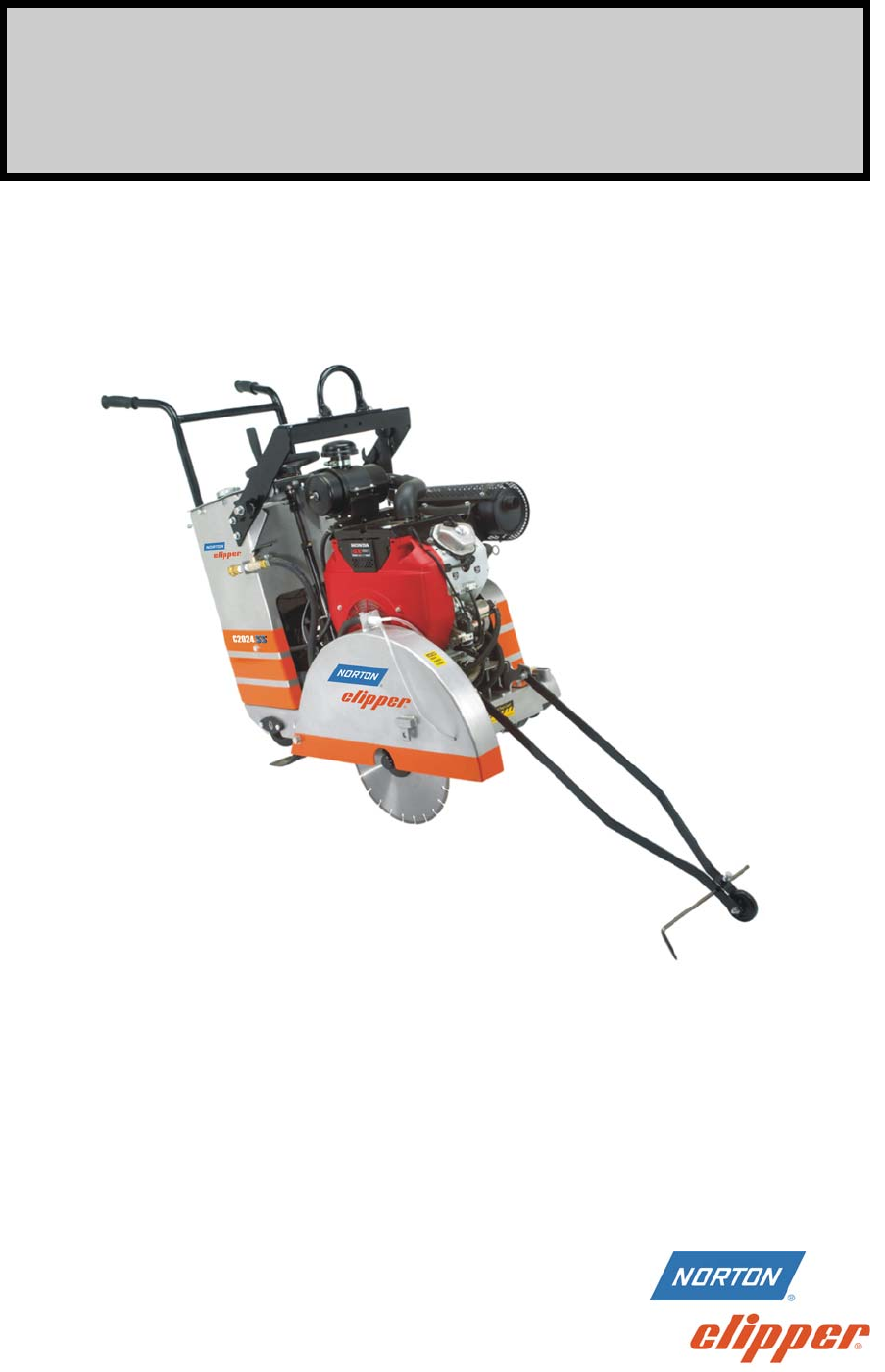
OWNERS MANUAL MEDIUM CONCRETE SAWS C1316SS C1320SS MODELS: C1316SM C1320SM C2016SS C2020SS C2024SS FORM C2020SS rev 5-11
WARRANTY Norton warrants all products manufactured by it against defects in workmanship or materials for a period of one (1) year from the date of shipment to the customer.
Table of Contents CONTENTS I. Preparation A. Safety Precautions B. Assembly C. Concrete Saw Specifications II. Operation A. Blade Installation B. Changing the Blade Side C. Starting The Engine D. Water Supply E. Controls F. Operating The Saw G. Cutting Technique H. Lead-Off Adjustment III. Maintenance A. Engine Engine Warranty B. Bearings C. V-Belts D. Depth Control E. Transmission F. Self-Propelling Unit G.
I. PREPARATION A. Safety Precautions Important! The following safety precautions must always be observed. Hazard Symbols Fuel (gasoline) is extremely flammable and its vapors can explode if ignited. Store gasoline only in approved containers, in well ventilated, unoccupied areas approved, and away from sparks or flames. Don not fill the saw fuel tank while the engine is hot or running. Do not start the engine near spilled fuel.
Dust and Silica Warning Grinding/cutting/drilling of masonry, concrete, metal and other materials can generate dust, mists and fumes containing chemicals known to cause serious or fatal injury or illness, such as respiratory disease, cancer, birth defects or other reproductive harm.
1. Before mounting any blade on the saw, the blade should be inspected for any damage which might have occurred during shipment, handling or previous use. 2. The blade collars and arbors should be cleaned and examined for damage before mounting the blade. 3. The blade must be properly fitted over the arbor with the drive pin on the outside collar projecting through the drive pin hole on the blade and inside collar. 4.
I. PREPARATION B. Assembly The self-propelled concrete saws are shipped completely assembled and ready for use except for diamond blade, gasoline, oil, and handle bar. Inspect the saw for shipping damage. If any damage is found, contact the shipper immediately and file a freight claim. The Norton Company is not responsible for any freight-related damages. Remove the saw from the pallet. Reverse the position of the handlebars so that the handle bar sticks out towards the operator.
C. C13xx/C20xx Concrete Saw Specifications Dimensions/Weight Length (Transport) Width Height Weights Engine Engine Mfg. Model Spec No.
II. OPERATION Read and understand this manual before running or using the machine! A. Installing the Blade 1. Insure that the Ignition Power Key Switch is in the OFF position and then disconnect the spark plug. 2. Remove the blade shaft nut, (NOTE: Operator’s Right side is a left hand thread and the Operator’s Left side is right hand thread), and remove the outside collar. Rotate the Blade Guard to gain better access to the Blade Shaft Nut, Loose Collar, Blade, and Tight Collar.
4. Inspect the blade for any damage, cracks, burnt or blue areas, missing segments, and roundness of blade. Also inspect the arbor hole and drive pin hole to insure both are round. If any problems are found do not use the blade. In addition check that the blade is the correct specification for the application. Use only Clipper Diamond Blades. This machine was not designed for the use with abrasive blades. 5.
8. Insure that the Blade Guard is lowered and the Blade Guard Locking pin is secure. Close Blade Guard Nose. See Blade Installed diagram below. Blade Installed 9. Reconnect the spark plug. Observe rotation arrow on blade and do not exceed maximum RPM stamped on blade. NOTE: Organic bonded blades (A) must have a blotter. The blotter (B) must extend past the blade collar contact area as shown.
B. Changing the Blade Side: 1. Insure that the Ignition Power Key Switch is in the OFF position and then disconnect the spark plug. 2. Remove the blade shaft nut, (NOTE: Operator’s Right side is a left hand thread and the Operator’s Left side is right hand thread), and remove the outside collar. 3.
Blade Shaft Guard Blade Shaft Guard Removal 7. Place the blade on the blade shaft, lining up the drive pin hole in the blade with the drive pinhole in the inside collar. NOTE: Diamond blades are direction dependent so verify the direction of rotation of the blade. The machine will rotate the blade into the work surface (down cut). 7. Slide the outside blade shaft collar onto the blade shaft. The drive pin on the outside collar must project through the drive pin hole in the blade and into the inside collar.
C. Engine Operation Prior to attempting to operate the engine, read the information contained in the engine owner's manual. An engine owner’s manual is supplied with every gasoline powered concrete saw. 1. Check Oil: Add oil if low. Refer to the engine owner's manual for the recommended SAE viscosity grades. Capacity of oil is 1.1 liters (1.16 US qt) 2. Check Fuel: Fill if low. Use only unleaded gasoline with a pump sticker octane rating of 86 or higher is recommended.
E. Controls Depth Control Hand Wheel Emergency Kill Switch Tachometer/Hour Meter Raise Levantar Engine Ignition Switch Blade Speed Chart Tabla de Velocidad Del Disco 3600 RPM Lower Bajar RPM/Hours (RPM/Horas) Blade Shaft Pulley Dia Eng Pulley Blade Shaft Blade Dia Eng rpm Diámetro en Diameter RPM Diametro de Flecha Disco Polea de Motor rpm Diámetro en Disco RPM Flecha Disco Polea Motor 16" (406mm) 3,600 rpm 3.15" (80mm) 2,520 rpm 4.5" (114mm) 16" (406mm) 3,600 rpm 3.
Transmission Engage/Disengage Lever: Controls the Engagement and Disengagement of the Transmission. Push down to Engage and pull up to disengage the transmission. Only operate the Transmission Engage/Disengage Lever when the machine is NOT moving. Operation of the Transmission Engage/Disengage Lever while the machine is moving may damage the Rear Wheels. When the Transmission Engage/Disengage Lever is in the Disengage position the machine can be moved with out the engine running.
Engine Ignition Switch: The Engine Ignition Switch allows the operator to start and stop the engine. Tachometer/Hour Meter: The Tachometer/Hour Meter shows the engine RPM only when the Engine is running. The total Engine operating hours (run time) are shown when the Engine is turned off. Emergency Kill Switch: The Emergency Kill Switch will stop the engine when depressed. The engine will not restart until the Emergency Kill Switch is pulled out.
Engine and Blade Speed Chart Blade Diameter 14" (356mm) 16" (406mm) 20" (508mm) 24" (609mm) Engine RPM Engine Pulley Diameter Blade Shaft RPM 3600 RPM 3.15" (80mm) 2520 RPM 3600 RPM 3.15" (80mm) 2520 RPM 3600 RPM 3.15" (80mm) 2520 RPM 3600 RPM 2.65" (67mm) 2120 RPM Blade Shaft Pulley Diameter 4.5" (114mm) 4.5" (114mm) 4.5" (114mm) 4.5" (114mm) 10. Slowly lower the blade by rotating the hand wheel clockwise until the desired depth of cut is reached. Use a reasonable rate of feed.
Caution: Do Not Engage Or Disengage The Transmission While The Machine Is In The Forward Or Reverse Positions! G. Cutting Technique Lower the blade into the concrete to the required depth by turning the hand wheel clockwise. Ease the handle slowly forward. Retard the forward pressure if the saw begins to stall. Note: For deeper cuts (4 inches or more), several cuts should be made in incremental steps of 1-1/2 to 2 inches until the desired depth of cut is reached.
G. Lead-Off Adjustment If the saw tends to pull to one side (lead off), it may be steered by applying slight pressure to the left or right hand handles.
III. MAINTENANCE A. Engine Maintenance Follow the below schedule for engine maintenance. NOTE: Check the Honda Engine manual that came with the engine for any changes to the maintenance schedule. If the charts have any differences, follow the chart in the Honda Engine Manual. The Norton Company does not warranty the engine. If any warranty or service of the engine is required contact your nearest Honda service center, or from the Internet: http://www.honda-engines.com/home.
Always refer to the engine manual for more detailed information on checking the oil, changing oil, and oil capacity, air filter changes, and fuel type to use. Use only Honda air filters. Do not clean the air filter with gasoline or other flammable solvents. A fire or explosion could result. To clean, follow the instructions found in the Honda engine manual.
B. Bearings Re lubrication type bearings must be relubricated daily to assure long life. The grease used should conform to the NLGI grade two consistencies and be free of any chemical impurities such as free acid or free alkali, dust rust, metal particles or abrasives. For best results, bearings should be relubricated while in operation. Note: Due caution for personal safety must be observed when servicing rotating equipment. The grease should be pumped in slowly until a slight bead forms around the seals.
C. V-Belts Warning: Never make adjustments to belts or pulleys while engine is running! 1. The best tension for a belt drive is the lowest tension at which the belts will not slip under full load. 2. Simply take up the drive until the belts are snug in the grooves. Run the drive for about 15 minutes to "seat" the belts. Then impose the peak load. If the belts slips tighten them until they no longer slip at peak load. 3. Remember too much tension shortens belt and bearing life! FIGURE 1 4.
D. Depth Control The depth control (raising screw) consists of a threaded rod which feeds into a brass nut. In order to keep the two parts working smoothly it is necessary to keep the rod free from dirt and sludge as much as possible. Cleaning the threaded rod with a rag after each use will prevent sludge from collecting in the tube assembly and protect the threads. It is a good practice to keep the raising screw threads lubricated, as the slurry generated during cutting will cause premature thread wear.
Raise Levantar Blade Speed Chart Tabla de Velocidad Del Disco 3600 RPM Lower Bajar RPM/Hours (RPM/Horas) Blade Shaft Pulley Dia Eng Pulley Blade Shaft Diámetro en Diameter RPM Diametro de Flecha Disco Polea de Motor rpm Diámetro en Disco RPM Flecha Disco Polea Motor 16" (406mm) 3,600 rpm 3.15" (80mm) 2,520 rpm 4.5" (114mm) Blade Dia Eng rpm 16" (406mm) 3,600 rpm 3.15" (80mm) Ignition Ignicion Emergency Stop Paro de Emergencia 2,520 rpm 4.5" (114mm) 20" (508mm) 3,600 rpm 3.
7. Start and test the machine. 8. If any problems are found repeat steps 1 to7.
G.
G. ELECTRICAL DIAGRAM C1316SM & C1320SM: 13HP Electric Start Models Only Spark Plug Transistorized Ignition Unit Oil Level Switch + Oil Alert Unit O (238033) Starter Motor Battery 12 volt ST 20A Charge Coil R (BL/R) (BL/R) BL (238035) (W) (G) (Y) (W) (W) IG R (238032) (Y) 15 Amp Fuse Change Honda Switch White Wire Ring Terminal To Female Bullet Connector 0.
G.
IV. PARTS LIST SECTION A. Ordering Information 1. List model number and serial number of machine. 2. List part number and serial number of part not the item number. 3. Wherever alternate parts are shown due to product improvement, inspect the part you have and provide additional description as necessary. 4. Specify mode of shipping desired, such as, parcel post, truck, U.P.S., best way, etc.
3 4 5 4 3 14 15 5 3 2 5 1 4 25 22 3 5 5 19 4 3 23 18 20 21 5 4 3 10 3 26 4 12 3 5 4 4 11 27 7 5 4 8 3 4 3 16 24 6 17 9 5 4 3 C13xx and C20xx Frame Common 33 4
C13xxx and C20xx Frame Common Item 1 2 3 4 5 6 7 8 9 10 11 12 -NA14 15 16 17 18 19 20 21 22 23 24 25 26 27 28 Req Part No.
12 13 2 4 9 1 5 11 7 8 4 6 4 14 2 4 13 5 10 4 14 3 4 6 1 4 C13xxx and C20xx Raise Axle 35 12
C13xx and C20xx Raise Axle ITEM 1 2 3 4 5 Req PART No.
3 4 7 5 6 8 9 2 4 2 2 1 19 13 14 15 16 22 10 39 11 12 2 18 11 19 11 17 12 32 11 See Detail "A" 24 33 35 Detail "A" 25 23 12 39 11 17 34 22 11 26 16 11 12 15 28 29 38 19 20 34 11 36 27 11 37 12 30 C13xxx and C20xx Transmission 37 21 22
C13xxx and C20xx Transmission ITEM 1 2 3 4 5 6 7 8 9 10 11 12 13 14 15 16 17 18 19 20 21 22 23 24 25 26 27 28 29 30 31 32 33 34 DESCRIPTION SPROCKET 35B12 X 17mm SCR 1/4-20 X 1/4 SET CUP ROLLER (1) BEARING FLANGE 3/4 B SPROCKET 35B48 X 34 B MASTER LINK CHAIN # 35 KEY 3/16 X 2 TRANSMISSION JACKSHAFT SCR 3/8-16 X 1 1/4 HEX HD CAP WASHER 3/8 SAE NUT 3/8-16 HEX LOCK TRANSMISSION MOUNT SCR 3/8-16 X 3 1/2 HEX HD CAP SCR 1/2-13 X 1 1/2 HEX HD CAP WASHER 1/2 SPRING LOCK WASHER 1/2 SAE TRANSMISSION M6 # 3 WOODRUFF
ITEM 35 36 37 38 39 DESCRIPTION WASHER 1/4 SPRING LOCK INTERNAL RETAINING RING 1 5/16" CONTROL LEVER PIN TRANSMISSION CONTROL SCR 3/8-16 X 2 HEX HD CAP 39 Req 1 1 1 1 2 PART No.
22 23 18 19 21 12 15 18 33 17 19 13 16 24 32 31 29 30 19 20 27 5 4 2 1 7 14 10 9 12 10 8 9 8 11 3 4 6 C13xxx and C20xx Blade Shaft & Engine Group 40
C13xxx and C20xx Blade Shaft & Engine Group ITEM DESCRIPTION 1 BLADE SHAFT TIGHT COLLAR RIGHT SIDE 2 Req 1 PART No. 238179 1 227159 3 TIGHT COLLAR LEFT SIDE 1 227190 4 LOOSE COLLAR OUTER FLANGE 2 227247 5 NUT BLADE SHAFT 3/4-16 LH x 1” LONG 1 227156 6 NUT BLADE SHAFT 3/4-16 RH x 1” LONG 1 7 8 9 10 11 12 13 14 BEARING PIL BLK 1-1/4 2-B SCR 1/2-13 X 1 1/4 HEX HD CAP WASHER 1/2 SPRING LOCK WASHER 1/2 SAE PULLEY 4.5OD X 1.
1 12 2 3 4 5 11 10 9 19 7 13 14 16 15 14 16 15 13 C13xxx and C20xx Blade Guard and Water System Group 42
C13xx and C20xx Blade Guard and Water System Group ITEM 1 2 3 4 5 6 7 8 DESCRIPTION HOSE SWIVEL WATER VALVE 1/2" HOSE BARB 1/2" x ½”MPT HOSE CLAMP SCR 1/4-20 X 1 HEX HD CAP WASHER 1/4 SAE FIT BARB HOSE 1/4MPTX1/2 “Y” FITTING x 1/4FPT 9 BLADE GUARD 16” Req PART No.
1 2 6 7 21 18 14 28 16 27 15 3 26 8 4 17 5 6 13 19 7 4 20 19 8 5 30 3 29 23 4 24 9 4 23 10 12 5 11 22 3 25 13 C13xxx and C20xx Controls and Console Group 44
C13xx and C20xx Controls and Console Group ITEM 1 2 3 4 5 6 7 8 9 DESCRIPTION HANDLE BAR HANDLE BAR GRIP SCR 3/8-16 X 1 1/4 HEX HD CAP WASHER 3/8 SAE ZN PLT NUT 3/8-16 HEX LOCK SCR 1/4-20 X 1 HEX HD CAP WASHER 1/4 SPRING LOCK WASHER 1/4 SAE FUEL TANK (20HP ONLY) THROTTLE CABLE 10 (INCLUDES CABLE AND CONTROL) 11 SWITCH IGNITION 20HP HONDA 11 SWITCH IGNITION 13HP HONDA 11 SWITCH IGNITION 13HP ES HONDA 12 13 14 15 16 17 18 19 20 21 TRANSMISSION CONTROL EMERGENCY KILL SWITCH NUT 1/4-20 HEX LOCK SPRIN
17 20 16 15 12 14 18 11 10 19 9 13 8 7 21 6 5 4 3 2 1 19 22 19 21 C13xxx and C20xx Depth Adjustment Group 46
C13xxx and C20xx Depth Adjustment Group ITEM 1 2 3 4 5 6 7 8 9 10 11 12 13 14 15 16 17 18 19 20 21 22 Req PART No.
2 1 9 4 8 5 10 3 7 4 To Blade Guard C13xxx and C20xx Optional Water Tank Group 48
C13xxx and C20xx Optional Water Tank Group ITEM -NA1 2 3 4 5 6 Req PART No.
Saint-Gobain Abrasives 2770 West Washington Stephenville, TX 76401 Phone: 254-918-2310 Fax: 254-918-2312 50