C-Touch Colour Touch Screen Installation Instructions 50xxCTC Series
© Copyright Clipsal Integrated Systems Pty Ltd 2005. All rights Reserved. This material is copyright under Australian and international laws. Except as permitted under the relevant law, no part of this work may be reproduced by any process without prior written permission of and acknowledgement to Clipsal Integrated Systems Pty Ltd. Clipsal and C-Bus are registered trademarks of Clipsal Australia Pty Ltd. The information in this manual is provided in good faith.
Contents 1.0 2.0 3.0 4.0 5.0 6.0 7.0 8.0 9.0 10.0 11.0 12.0 13.0 14.0 15.0 16.0 17.0 Product Range Important Notes Description 3.1 Packing List 3.2 Features 3.3 Infrared Remote Control Definitions Installation Procedure 5.1 Location 5.2 Multiple C-Touch Units Mounting Instructions 6.1 Nail Bracket 6.2 Wall Box 6.3 The Power Supply Unit 6.4 Attaching the Facia Wiring Details 7.1 C-Bus Network Connection 7.2 Programming Lead 7.3 Audio and IR Connections 7.4 Video Connection 7.
C-Touch Colour Touch Screen 4
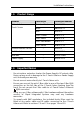
Installation Instructions 1.0 Product Facia Style Catalogue Number C-Touch Colour Touch Screen Stainless Steel BS5000CTC Brass BB5000CTC Neo 5050CTC Glass, Cream 5080CTC-3 Glass, Black 5080CTC-6 Glass, Mid-Brown 5080CTC-7 Glass, White 5080CTC,GF Infrared Remote Control — 5035TX Nail Bracket — 5000CTCNA Wall Box — 5000CTCWB Power Supply — 5000CTCPS 2.0 • • • • • Product Range Important Notes Do not replace, extend or shorten the Power Supply’s DC output cable.
C-Touch Colour Touch Screen • Cabling for this product should be performed by a suitably qualified person, in accordance with the laws and requirements of the state or country of installation. Do not over tighten the screws when securing the C-Touch Colour unit to the wall. Doing so may distort the casing, making attachment of the facia more difficult. • 3.0 Description The C-Touch Colour Touch Screen (C-Touch Colour) allows sophisticated control of an entire C-Bus system from one location.
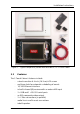
Installation Instructions Figure 1 – Typical components packed with the5080CTC, GF C-Touch Colour 3.2 Features The C-Touch Colour’s features include: • • • • • • • • • a touch sensitive 6.4 inch (16.
C-Touch Colour Touch Screen 3.3 Infrared Remote Control The C-Touch Colour is equipped with an Infrared Remote Control, used to select scenes and switch loads on, off, or adjust their level. The remote control functionality is incorporated into a software project. The available functions depend on how the C-Touch Colour is programmed. If multiple C-Touch Colour units are installed, the same remote control can talk to each of them. Figure 2 – The Infrared Remote Control 4.
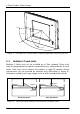
Installation Instructions 5.0 Installation Procedure 5.1 Location It is important to select the right location to install the C-Touch Colour. Some considerations: • The unit has a typical viewing angle of 70° to the left, right and down, and 40° up (illustrated in Figure 3). Take this into account when choosing the mounting height. • Provide easy access to the unit for switching lights and selecting scenes.
C-Touch Colour Touch Screen 40° up 70° left 70° down 70° right Figure 3 – Consider the C-Touch Colour's viewing angle when mounting the unit 5.2 Multiple C-Touch Units Multiple C-Touch units can be installed on a C-Bus network. These units may be programmed to operate cooperatively or independently of each other. Take care not to mount units where a single IR remote control transmission can be received by multiple units (illustrated in Figure 4).
Installation Instructions 6.0 Mounting Instructions There are two options for mounting the C-Touch Colour. These are: • • 6.1 in stud walls (such as timber frame internal walls) using a nail bracket in solid walls (such as brick or stone) or stud walls using a wall box. Nail Bracket The C-Touch Colour Nail Bracket (part number 5000CTCNA) provides a convenient means of mounting the C-Touch Colour unit.
C-Touch Colour Touch Screen To mount the C-Touch Colour using the nail bracket: 1) Place the bracket against a beam of the wall frame. 2) Nail the bracket into the frame. Alternatively mark and drill the holes, then screw the bracket into the frame. 3) Feed the cables through to the nail bracket. The use of conduit is recommended. Refer to Figure 6. The number and positioning of cables will vary depending on the particular installation. Possible cables are listed in Table 1.
Installation Instructions Figure 6 – Installing the C-Touch Colour Nail Bracket 13
C-Touch Colour Touch Screen 6.2 Wall Box The C-Touch Colour Wall Box (part number 5000CTCWB) allows the C-Touch Colour unit to be mounted within a solid wall construction such as brick or stone. It provides increased RF shielding compared to the Nail Bracket. The wall box (illustrated in Figure 7) may also be used to mount a C-Touch Colour unit in timber or metal framed stud walls.
Installation Instructions Figure 8 – Installing the C-Touch Colour Wall Box 6.3 The Power Supply Unit It is recommended that the 5000CTCPS Power Supply be mounted above the C-Touch Colour unit in the ceiling space. Note the following important points: • • • • Do not cover the power supply unit or sandwich it between cavities or insulation. Feed the DC output cable down to the C-Touch Colour unit through conduit.
C-Touch Colour Touch Screen 6.4 Attaching the Facia The following steps are illustrated in Figure 9. To attach the facia: 1) Position the facia over the touch screen, with the IR and indicator windows on the right hand side. Ensure that the clips on the left underside of the facia are positioned just left of the matching clips on the C-Touch Colour unit. 2) While applying forward pressure on the left side of the facia (toward the touch screen), push the left side to the right.
Installation Instructions To remove the facia: 1) Grasp the right side of the facia with your left hand. 2) Push the release lock in with your right thumb. At the same time lift the right side of the facia plate off and to the right with your left hand (to disengage the clip. 3) Swing the facia off towards the left. Refer to Figure 10. Push the release lock Lift off and to the right to disengage the clip, then swing to the left Figure 10 – Removing the facia 7.0 Wiring Details 7.
C-Touch Colour Touch Screen C-Bus Positive: blue + orange C-Bus Negative: blue & white + orange & white Remote OFF: brown + brown & white Remote ON: green + green & white Figure 11 – C-Bus cable conductor assignments Pin C-Bus Connection Colour 1 Remote ON green & white 2 Remote ON green 3 C-Bus Negative (-) orange & white 4 C-Bus Positive (+) blue 5 C-Bus Negative (-) blue & white 6 C-Bus Positive (+) orange 7 Remote OFF brown & white 8 Remote OFF brown 87654321 87654321
Installation Instructions 7.2 Programming Lead A programming lead is provided with the C-Touch Colour unit. It consists of a Cat-5 crossover Ethernet patch cable. Use the crossover programming lead when connecting directly from a PC (e.g. laptop) to the C-Touch Colour. If connecting through a network hub or switch, you will need to use a standard Ethernet cable. Cable conductor assignments for a crossover Ethernet cable are shown in Table 3.
C-Touch Colour Touch Screen Figure 12 – Audio and IR cables must be looped through the large ferrite filter 7.4 Video Connection An RCA video out connection is provided on the bottom right side of the C-Touch Colour. This allows the unit’s display to be viewed on a TV or monitor which has a composite video input. If the video out connection is utilised, it is important that the smaller ferrite filter (provided) is fitted over the video cable.
Installation Instructions 7.5 RS-232 Connection The RS-232 serial port connection uses standard EIA 574 pinouts (provided in Table 4). The RS-232 port allows you to connect external devices to the C-Touch Colour, such as security and control equipment. If using the RS-232 port to connect to external devices, ensure you use a suitable shielded data cable. Cable length should be limited to 15 metres for communication at up to 19,200 bps, or 7.5 metres at 38,400 bps.
C-Touch Colour Touch Screen 9.0 C-Bus Power Requirements The C-Touch Colour draws 20 mA from the C-Bus network. Adequate C-Bus power supply units must be installed to support connected devices. If in doubt, refer to the C-Bus Training Manual. The C-Bus Calculator software is useful in determining power supply requirements. Note that factors such as even power supply distribution and cable length have an impact on the actual power requirements. 10.
Installation Instructions 12.0 Programming Requirements Unit Address The C-Touch Colour must be programmed with a unique identification address (Unit Address). This is accomplished using the C-Bus Toolkit software, available from the downloads section of the Clipsal Integrated Systems (CIS) web site (http://www.clipsal.com/cis). The C-Bus Toolkit is also used to enable the C-Bus System Clock and burden if required.
C-Touch Colour Touch Screen 1) Once the C-Touch Colour has been installed and switched on, you should see the default screen in Figure 14. You must configure the unit with an IP address and customised project file, before it is ready for use. Figure 14 – The initial screen of an unconfigured C-Touch Colour Touch Screen 2) Remove the facia if it has been fitted to the unit (refer to page 17).
Installation Instructions Figure 15 – Select the network card used to connect to the C-Touch Colour 7) The software will search for C-Touch Colour Touch Screen units. It is likely that none will be found. If the C-Touch Colour unit has been found, go to step 12. 8) You will be asked to select the type of network (Figure 16). Select Standalone, and click Next.
C-Touch Colour Touch Screen 9) The Transfer Utility software will suggest an IP Address to be programmed into the C-Touch Colour unit (Figure 17). This address is chosen to be compatible with the PC you are using. It is sent to the C-Touch Colour which will ask you to confirm the new IP Address (Figure 18). Press Yes on the C-Touch Colour unit.
Installation Instructions Figure 19 – The Address Type has been set 11) Click Next on your PC. The Transfer Utility software will again search for the C-Touch Colour unit. 12) You will be presented with a list containing the found unit (Figure 20). Ensure the unit is selected (click on its name to highlight it), and click Finish.
C-Touch Colour Touch Screen 13) The Transfer Utility software will display the Information page for the connected C-Touch Colour unit (Figure 21). Two other pages, Control and Transfer, can be selected by clicking the appropriate tab. Figure 21 – The Information page in the Transfer Utility software 14) Click the Transfer tab to select the Transfer page shown in Figure 22. From here you can transfer a project to the C-Touch Colour Touch Screen.
Installation Instructions Figure 22 – The Transfer page in the Transfer Utility software 15) Select the ‘…’ button adjacent to the Project File Location field (Figure 23), and choose the project archive to be transferred.
C-Touch Colour Touch Screen 16) Click the “Transfer Project To C-Touch Colour” button (Figure 24). Figure 24 – Transfer the project to the C-Touch Colour 17) Depending on its size, the project may take from one to many seconds to transfer. Once the project has been successfully transferred, you will be advised that the project has been uploaded (Figure 25).
Installation Instructions Figure 26 – The Control page in the Transfer Utility software 19) Ensure that the time on your PC is set correctly. If not, change the time. This can be accomplished by double clicking the clock on the bottom right of the screen (if present). 20) Click the “Set Time” button in the Transfer Utility software. This will set the time on the C-Touch Colour to the time set on your PC. No feedback is given to indicate the time on the C-Touch Colour has been set.
C-Touch Colour Touch Screen 14.0 Electrical Specifications C-Touch Colour Touch Screen Parameter Description Supply voltage 5 V DC, 30 W maximum via power pack* Display type 6.
Installation Instructions Infrared Remote Control Parameter Description Supply voltage 3 V DC required for normal operation.
C-Touch Colour Touch Screen 15.0 Mechanical Specifications C-Touch Colour Touch Screen Parameter Description Dimensions (W×H×D) 246 x 173 x 72.5 mm (excluding facia) Protrusion from wall 23.5 mm (including glass facia) Mounting depth (into wall) 54 mm Mounting centres (H×V) 212.5 × 112 mm Weight 1375 g (excluding facia) 246 mm 202 mm 18.
Installation Instructions Infrared Remote Control Parameter Description Dimensions (W×H×D) 86 × 54 × 8 mm Weight 28 g Colour black Nail Bracket Parameter Description External dimensions (W×H×D) 287 × 215 × 47 mm Cut-out dimensions (W×H) 205 × 162 mm Weight 530 g Wall Box Parameter Description External dimensions (W×H×D) 224 × 167 × 68 mm Internal dimensions (W×H×D) 219 × 162 × 66.
C-Touch Colour Touch Screen 16.0 Standards Complied DECLARATIONS OF CONFORMITY Australian/New Zealand EMC & Electrical Safety Frameworks and Standards The C-Touch Colour Touch Screen complies with the following: Regulations EMC (C-Tick) Safety Standard AS/NZS CISPR 22 (Class A) Title IT Equipment Emissions Standard AS/NZS CISPR 24 IT Equipment Immunity Standard AS/NZS 60950.
Installation Instructions 17.0 Warranty The C-Touch Colour product carries a two year warranty against manufacturing defects (refer to the Warranty Statement), with the exception of the 5035TX Infrared Remote Control’s battery which is limited to 30 days.
C-Touch Colour Touch Screen 38
Technical Support and Troubleshooting For further assistance in using this product, consult your nearest Clipsal Integrated Systems Sales Representative or Technical Support Officer. Technical Support Hotline: 1300 722 247 (Australia) 0800 888 219 (New Zealand) Technical Support Email: techsupport.cis@clipsal.com.au Sales Support Email: sales.cis@clipsal.com.au A list of worldwide contacts, additional product information and technical resources is provided at http://www.clipsal.