C-Touch Colour Touch Screen 50x0CTC3 Series Installation Instructions
50x0CTC3 Series C-Touch Colour Touch Screen Installation Instructions Contents 1.0 Product Description ........................................................................................3 1.1 Features and Capabilities ..........................................................................3 1.2 Infrared Remote Control ............................................................................6 1.3 Definitions ........................................................................................
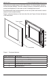
50x0CTC3 Series C-Touch Colour Touch Screen Installation Instructions 1.0 Product Description The C-Bus C-Touch Colour Touch Screen provides sophisticated control of an entire system from one location. Using the appropriate software, you can: • configure the screens (pages) for convenience of use • control devices, scenes and schedules • configure an audible alarm • display video from a camera connected to the local LAN. Several fascia colour and style options are available.
50x0CTC3 Series C-Touch Colour Touch Screen Installation Instructions The touch screen is powered by the power supply listed in Table 1. The touch screen does not supply power to the C-Bus network. An internal battery maintains the time and date settings. The touch screen’s processor automatically controls the contrast and brightness of the screen as well as backlight level control. By setting access levels and passwords, you can set up the touch screen to restrict access to touch screen functions.
0x0CTC3 Series C-Touch Colour Touch Screen Installation Instructions DC IN + - Figure 2. Back panel connection points. Figure Reference Connections and Features Description 1 Ethernet LAN RJ45 2 Memory card Compact Flash 3 C-Bus network 2 x RJ45 4 Serial interface DE9 5 IR control input 3.5mm mono jack 6 Audio line input 3.5mm stereo jack 7 Audio line output 3.5mm stereo jack 8 USB 2 x USB A 9 Power supply 2-terminal plug 10 Keyboard PS/2 © 2012 Schneider Electric.
50x0CTC3 Series C-Touch Colour Touch Screen Installation Instructions 1.2 Infrared Remote Control The touch screen is supplied with an infrared remote control that is used to trigger scenes, switch loads and adjust lighting levels. The remote control functions are incorporated into a software project. During programming, the functions available to the remote control are set. If multiple touch screen units are installed, the same remote control can talk to each of them. Figure 3.
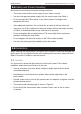
50x0CTC3 Series C-Touch Colour Touch Screen Installation Instructions 2.0 Safety and Product Handling Be aware of the following information during installation: • The touch screen and its power supply are for indoor use only. • Use only the approved power supply with the touch screen (see Table 1). • Do not connect the C-Bus cables to any other network. Damage to the equipment will occur. • Allow adequate ventilation. Do not block the air vents at the top of the unit.
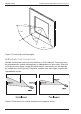
50x0CTC3 Series C-Touch Colour Touch Screen Installation Instructions 60˚ up 70˚ left 60˚ down 70˚right Figure 4. Touch screen viewing angles. 3.2 Multiple Touch Screen Units Multiple touch screen units may be installed on a C-Bus network. These units may be programmed to operate cooperatively or independently of each other. Take care not to mount units where a single IR remote control transmission can be received by multiple units (see Figure 5).
50x0CTC3 Series 3.
50x0CTC3 Series C-Touch Colour Touch Screen Installation Instructions 5. Place the side clamps so that they clamp the bracket to the plasterboard and then tighten the side clamp screws. 6. Connect the cables to the back of the touchscreen. Refer to the wiring instructions. 7. Carefully place the touch screen in the bracket and use the four long screws to fasten the unit in place.
50x0CTC3 Series C-Touch Colour Touch Screen Installation Instructions Figure 8. Nail bracket installation detail Wall Box The C-Touch Colour Wall Box, catalogue number 5000CTCWB, allows the touch screen to be mounted in a solid wall construction such as brick or stone. It provides better RF shielding than the nail bracket. The wall box may also be used to mount the touch screen in timber or metal-frame stud walls.
50x0CTC3 Series C-Touch Colour Touch Screen Installation Instructions Figure 10. Wall box installation To mount the touch screen in the wall box, do the following: 1. Before rendering or plastering, attach the wall box to masonry or a beam of the wall framing. 2. Feed the signal and power cables through the holes in the wall box. The use of conduit is recommended (refer to Figure 10). 3.
50x0CTC3 Series C-Touch Colour Touch Screen Installation Instructions 3.4 Attaching and Removing the Fascia The following steps are illustrated in Figure 12. To attach the fascia: 1. Position the fascia over the touch screen, with the IR and indicator windows on the right hand side. Ensure that the clips on the left underside of the fascia are positioned slightly to the left of the matching clips on the touch screen. 2.
50x0CTC3 Series C-Touch Colour Touch Screen Installation Instructions To remove the fascia: 1. Grasp the right side of the fascia with your left hand. 2. Push the release lock in with your right thumb. At the same time lift the right side of the fascia plate off and to the right with your left hand (to disengage the clip). 3. Swing the fascia off towards the left. Refer to Figure 13. Push the release lock Lift off and to the right to disengage the clip, then swing to the left Figure 13.
50x0CTC3 Series C-Touch Colour Touch Screen Installation Instructions 4.0 Wiring Details All of the wired cable connections to the touch screen use quick disconnecting type plugs. Be sure to connect the cables to the correct locations before installing the touch screen in its mounting bracket with the four mounting screws. 4.1 C-Bus Network Connection Caution The C-Bus network must not be connected to any other type of network.
50x0CTC3 Series 4.2 C-Touch Colour Touch Screen Installation Instructions Audio and IR Connections If the touchscreen will use the audio input, audio output (3.5mm stereo sockets) and IR input (3.5mm mono socket) connections, it is important to use shielded cables and to keep the cables away from building power wiring or sources of interference such as lamp ballasts or motors. Figure 14. Audio and IR cable plugs 4.3 Power Supply Connection A building power outlet is required for the supply.
50x0CTC3 Series 4.4 C-Touch Colour Touch Screen Installation Instructions USB Connections One or two optional USB devices can be installed in the sockets on the rear panel. Using a USB extension cable is recommended for all devices. When using extension cables, place any USB devices outside of the metal box (see Figure 16). USB extension Adapter Figure 16. USB device and extension cable. To install the adapter, follow these steps: 1.
50x0CTC3 Series 4.6 C-Touch Colour Touch Screen Installation Instructions Wired LAN Connection Caution The Ethernet LAN network cable must not be connected to the C-Bus cable connector on the back panel. The two networks are not electrically compatible and improper connection will cause damage to the equipment. The 5000CTC3 touch screen supports a wired Ethernet LAN connection at the rear panel. The connection method used is a matter of choice.
50x0CTC3 Series C-Touch Colour Touch Screen Installation Instructions 5.0 C-Bus Programming Requirements Unit Address The touch screen must be programmed with a unique identification address (unit address). This is accomplished using C-Bus Toolkit software, available from the Downloads section of the Clipsal Integrated Systems (CIS) web site at: http://www.clipsal.com/cis. System Clock and Burden C-Bus Toolkit is also used to enable the system clock and burden, if required.
50x0CTC3 Series C-Touch Colour Touch Screen Installation Instructions 6.0 Using the C-Touch Colour Utility The C-Touch Colour Transfer Utility transfers a software project to the touch screen. The utility is included with PICED software that is available from the Downloads section of the CIS web site: http://www.clipsal.com/cis. This section takes you through the process of installing a project on the C-Touch touch screen using a direct Ethernet connection.
50x0CTC3 Series C-Touch Colour Touch Screen Installation Instructions 2. If your PC and the touch screen are both connected to a common Ethernet network, start the C-Touch Transfer Utility by clicking the C-Touch Transfer Utility in the PICED folder in the windows start menu, or select ‘Transfer to Unit’ in PICED‘s Transfer menu and continue to Step 11. If both devices are not connected to a common network, continue with Step 3. 3. Remove the fascia if it has been fitted to the unit. 4.
50x0CTC3 Series 8. C-Touch Colour Touch Screen Installation Instructions You will be asked to select the type of network. Select Direct Connect and then click OK (see Figure 19). Figure 19. Select the network connection type 9. The transfer utility software will suggest an IP Address for the touch screen (see Figure 20). Click Next to attempt to set the IP Address for the touch screen that is connected to your PC. You will be asked to confirm the suggested IP Address on the touch screen. Figure 20.
50x0CTC3 Series C-Touch Colour Touch Screen Installation Instructions 10. You will now see the touch screen unit listed in the transfer utility (see Figure 21). Figure 21. List of touch screens located by the search 11. Select the touch screen to be configured. The screen provides information about the selected touch screen (see Figure 22). Figure 22. Touch screen information screen 12.
50x0CTC3 Series C-Touch Colour Touch Screen Installation Instructions 13. Click the Transfer tab to select the transfer page. The transfer options allow you to transfer a project to the touch screen or transfer a project or log file to your PC. 14. Select the button for the Transfer Project to C-Touch Colour. Choose the project that was created for this touch screen installation. Then press Start to begin the transfer process. It may take several minutes for the transfer to complete.
50x0CTC3 Series C-Touch Colour Touch Screen Installation Instructions 15. Click the Control tab to select the Control page. From the control screen, you can take a screen grab of the touch screen and change the name that identifies the touch screen over the Ethernet connection (see Figure 25). Figure 25. Changing the name of the C-Touch Colour unit Figure 26. Confirming the name change Note: Using the touch screen on a network is similar to direct connection.
50x0CTC3 Series C-Touch Colour Touch Screen Installation Instructions 7.0 Reset Button In the event that the C-Touch Colour software becomes unresponsive, you can reset the touch screen by pressing the reset button. The reset button is located to the right of the display, beneath the fascia (see Figure 27). Instructions for removing the fascia are provided earlier in this document. Fascia release latch Reset button IR sensor Light sensor Figure 27.
50x0CTC3 Series C-Touch Colour Touch Screen Installation Instructions 8.0 Specifications 8.1 Touch Screen Specifications Parameter Description Power supply rating 24V d.c., 2.7A, class 2 Display type 16.3cm (6.4 in.
50x0CTC3 Series 8.2 C-Touch Colour Touch Screen Installation Instructions Touch Screen Dimensions Parameter Description Dimensions (W x H x D) 246 x 173 x 72.5mm (excluding fascia) Protrusion from wall 23.5mm (including fascia) Mounting depth (into wall) 54mm Mounting centres (H x V) 212.5 x 112mm 24 6 mm 202 mm 18.5 mm 54 mm 158 mm 173 mm 234 mm Note: 28 of 36 The touch screen in this example has a bevelled glass fascia. © 2012 Schneider Electric. All Rights Reserved.
50x0CTC3 Series 8.3 C-Touch Colour Touch Screen Installation Instructions Infrared Remote Control The 5035TX2 5-button remote control is supplied with the touch screen. You may purchase the 8-button version, if desired. Both types are described in the following table. Parameter Description Supply voltage 3V d.c. battery powered. Transmission range reduces with decreasing battery voltage.
50x0CTC3 Series 8.
50x0CTC3 Series C-Touch Colour Touch Screen Installation Instructions 9.
50x0CTC3 Series C-Touch Colour Touch Screen Installation Instructions US FCC Regulations (continued) Class B Product Note: This equipment has been tested and found to comply with the limits for a Class B digital device, pursuant to Part 15 of the FCC Rules. These limits are designed to provide reasonable protection against harmful interference in a residential installation.
50x0CTC3 Series C-Touch Colour Touch Screen Installation Instructions 10.0 Two-Year Warranty The 5000CTC3 Series C-Touch Colour Touch Screen carries a two-year warranty against manufacturing defects. Warranty Statement The benefits conferred herein are in addition to, and in no way shall be deemed to derogate, either expressly or by implication, any or all other rights and remedies in respect to the Clipsal by Schneider Electric product, that the consumer has in the location where the product is sold.
50x0CTC3 Series C-Touch Colour Touch Screen Installation Instructions Notes: 34 of 36 © 2012 Schneider Electric. All Rights Reserved.
50x0CTC3 Series C-Touch Colour Touch Screen Installation Instructions Notes: © 2012 Schneider Electric. All Rights Reserved.
Technical Support For further assistance in using this product, consult your nearest Clipsal Integrated Systems (CIS) Sales Representative or Technical Support Officer. Technical Support Contact Numbers Australia 1300 722 247 (CIS Technical Support Hotline) New Zealand 0800 888 219 (CIS Technical Support Hotline) United States 1 888 778 2733 lightingcontrol.support@us.schneider-electric.com Technical Support email: cis.support@clipsal.com.au Schneider Electric (Australia) Pty Ltd Contact us: clipsal.