
Specifications


Multi Room Audio Matrix Switcher and System Installation Instructions
9
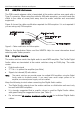
2.1 AM/FM Antenna
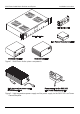
The RG6 coaxial antenna cable is terminated at the matrix switcher rear panel with a
Type-F connector. When using the cable for AM radio reception, you must break the
shield in the cable at some point away from the matrix switcher and associated
equipment.
Figure 5 shows the cable modification required for AM reception. It is not required if
you are using only FM reception.
Figure 5. Cable modification for AM reception
Refer to the Application Notes and the MARPA Help for more information about
selecting radio station presets.
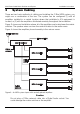
2.2 Digital Audio
The matrix switcher sends the digital audio to each MRA amplifier. The Cat.5e Digital
Audio cables are terminated at the matrix switcher using an RJ45 plug. The cable
carries:
• Digital audio signal
• 27 V d.c. to power the amplifier (see Note)
• Signals for infrared (IR) reticulation
Note: The matrix switcher can provide power for multiple MRA amplifiers using the Digital
Audio cable to distribute power. If you need more audio output power for an
amplifier, an external power supply can be installed.
Keep the following in mind when connecting the Digital Audio cables:
• The Digital Audio outputs from the matrix switcher or distribution unit must only
be used with MRA amplifiers.
• It is strongly suggested that a specific colour is used for Digital Audio cables,
with green being the suggested colour (see Table 2).
• Do not exceed 45 metres maximum cable length for individual Digital Audio
cables.