
Specifications


C-BUS TRAINING MANUAL - VOL 2
102
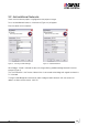
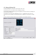
After you have added the Network bridge the following box (Figure 7) will appear which requests you
to enter the Serial Number and/or Tag of both sides of the bridge. Entering this information helps
quickly identify a particular bridge on larger Networks.
Figure 10 - Bridge Serial Number
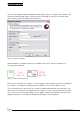
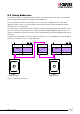
Network Addresses are determined by the unit address of the other side of the bridge that is
connected to this Network.
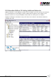
Figure 11 - Network Topology Layout
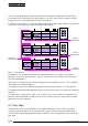
Note that the Local Network is address = 254, the bridge is represented by the box with the diagonal
line through it. The bridge on the opposite side to Network 254 has the unit address of 254.
This can be explained an alternative way, consider an adjoining door between two hotel rooms, the
door in room 254 would have the adjacent rooms number on it, hence showing where you are going.
This is the same with the Network bridges the unit address identifies the Network on the other side.
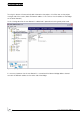
Additional Networks can be added as required by following the same procedure.