
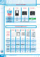
Specifications

13Home Networking Solutions
Demand the Best - Denand Digital Ready
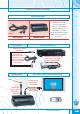
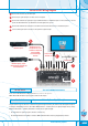
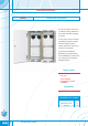
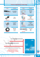
StarServe VDU Wiring Diagram
1
Connect the antenna to the antenna input.
2
Connect up to eight televisions or videos to the TV outputs.
3
Connect the modulator (if required) for pay TV, DVD and videos to modulator input ‘B’. This connection is used to
power the VDU and allow for the distribution of IR throughout the system.
4
Connect the modulator (if required) for surveillance cameras and other devices to modulator input ‘A’.
5
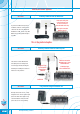
Use the variable gain control to adjust to the optimum signal strength.
In the event of FM interference affecting TV channels switch to ‘ON’ position.
NOTE: When ‘ON’ FM radio frequency will be blocked to all outputs.
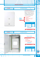
FM Trap Switch Filter out Unwanted Interference
The gain control is used to increase or decrease the signal strength received by the antenna. The ideal signal strength for
an analogue and digital TV Service is 65-74dbuV. Maximum Gain = +5 dbuV (increase in signal strength). Factory setting
Maximum Attenuation = -15dbuV (attenuation is the decrease of signal strength).
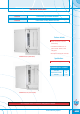
• The adjustment of signal strength to all outlets is made easy.
• The Video Distribution Unit (VDU) is treated as ONE TV OUTLET when choosing an appropriate antenna.
Gain Control Achieve Optimum Signal Strength
Filter out Unwanted Interference
nt
To all TVs, DVDs
and videos, etc
Modulator input ‘A’ is
used for devices such as
surveillance cameras that
are not controlled
via infrared through
StarServe
Modulator input ‘A’
Modulator input ‘B’ enables
remote powering of the VDU and
IR control of devices
Antenna Input
1
2
3
4
5