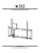
AUTOMATED TILT MOUNTING SYSTEM MANUAL FOR MODEL NUMBERS: TP150B AND TC105B CLO SYSTEMS, LLC 1501 W. Cameron Ave., Suite 215, West Covina, California 91790 T (626) 939-4226 / F (626) 939-3378 WWW.CLOSYSTEMS.
CAUTION: When using this automated tilt mounting system, basic precautions should always be followed, including: Follow the entire installation/user’s manual and the important safety instructions before attempting to install or use this mounting system. • Manufacturer is not liable for damage or injury caused by incorrect mounting, assembly, or use. • The maximum weight this mounting system can support varies depending on the model number.
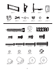
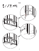
5mm (3/16 in.) 13mm (1/2 in.) Supplied Parts and Hardware Before starting assembly, verify all parts are included and undamaged. If any parts are missing or damaged, do not return the item to your dealer; contact the customer service number listed on the cover page 1. Never use damaged parts! Hardware and procedures for multiple mounting configurations are included. When you see this symbol, choose the correct configuration to suit your needs. Not all hardware included will be used.
[01] x 1 [06] x 1 [07] x 1 [02] x 1 [03] x 1 [08] x 1 [09] x 1 [04] x 1 [10] x 1 5/16 in.
1.0 5 mm 3/16 in. 30.4 ~ 61.0 cm (12 ~ 24 in.) 6.35 cm (2.5 in.
1.0. Wood Stud Wall Mounting Applications CAUTION: This product is not designed for use in metal stud walls. Do not over tighten the lag bolts [12]. Tighten the lag bolts only until they are firmly against the wall brackets [01]. Mount the wall bracket [01] to at least two (2) wooden studs spaced a minimum of 12 in. (30.4 cm) to a maximum of 24 in. (61.0 cm) apart. Do not mount this mounting system to wooden studs smaller than 2 in. x 4 in. (51.0 mm x 102.0 mm).
1.1 13 mm 1/2 in. >46 cm (18 in.) >15 cm (6 in.) >15 cm (6 in.) >30 cm (12 in.) >64 m m (2.5 in.) [14] >30 cm (12 in.) >15 cm (6 in.
1.1. Solid Concrete Wall Mounting Applications CAUTION: Make sure concrete anchors [14] are seated flush with concrete surface. The gypsum drywall, lath, plaster, and the like covering may not exceed 1/2 in. (12.7 mm) thickness. CAUTION: Do not over tighten the lag bolts [12]. Tighten the lag bolts only until they are firmly against the wall brackets [01].
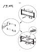
2.0 <=800 mm (31.5 in.) TP150B [03] [02] [04] Digital optical audio output > 38.1 mm (1.5 in.) [15, 16, 17, 18] [23, 24, 25, 26] [29, 30] 9 > 38.1 mm (1.5 in.
2.0. Mounting TV with a flat back Note: The plastic cover (shown in dotted lines) is only provided on model number TP150B; but NOT on model number TC105B. The pin [04] is shipped pre-inserted into the “STORE” opening on the bracket [03]. Note: Most flat screen TVs are provided with Digital Optical Audio Output on the back of the TV. If your TV has one, locate the Digital Optical Audio Output – as this will be used later.
2.1 <=800 mm (31.5 in.) TP150B [03] [02] [04] Digital optical audio output > 38.1 mm (1.5 in.) [19, 20, 21, 22] [23, 24, 25, 26] [29, 30] [29] OPT [27, 28] 11 > 38.1 mm (1.5 in.
2.1. Mounting TV with a curved back or obstruction Note: The plastic cover (shown in dotted lines) is only provided on model number TP150B; but NOT on model number TC105B. Note: Most flat screen TVs are provided with Digital Optical Audio Output on the back of the TV. If your TV has one, locate the Digital Optical Audio Output – as this will be used later.
3.
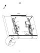
3.0. Hang TV onto the wall bracket You may need assistance with lifting the TV. Remove the two screws on the bottom of the two brackets [02] and [03], and save these screws as they will be used in the following steps. Hang the two brackets [02] and [03] to the wall bracket [01]. Reinsert and tighten the bottom two screws to anchor the motorized bracket [02] and the non-motorized bracket [03] to the wall bracket [01].
4.
4.0. Electrical Connections Note: Select the right electrical prong [09, 10, or 11] for your electrical socket. (1) Refer to Section 9.0 and manually tilt the TV up, and insert the pin [04] to the “UP” opening to hold the TV up for easier electrical connections. (2) Insert the AC adapter jack [06] into the control box, and plug in the electrical prong to electrical socket. (3) Insert the IR receiver jack [07] into the control box, and attach the head of the IR receiver [07] to the bottom of the TV.
5.
5.0. Adjusting the Tilt Note: Section 5.0 only applies to Model Number TP150B. For Model Number TC105B, skip this Section and go to the Section 7.0 (1) Use the down arrow button ( ) on the remote control [05] to fully tilt down the TV. Refer to Section 9.0. (2) The mounting system is design to tilt the TV down maximum of 13º. Note: the maximum tilt angle may vary depending on the application such as the support wall and the weight of the TV. (3) Visually check to see if the TV tilts down fully.
6.
6.0. Removing the spring to tilt the TV down fully Make sure the TV is in the upright position before proceeding with these steps! (1) If the TV is not in the upright position, then use the up arrow button ( the TV. ) on the remote control [05] to tilt up (2) Remove the two screws to take of the plastic cover off on the non-motorized bracket [03]. (3) Remove the screw holding the lever. (4) Lower the lever to take the spring off. (5) Return the lever to the original position.
7.
7.0. Optional: Adjusting the upright position of the TV If desired, adjust the upright position of the TV by ± 2º by turning the bottom screw on the motorized bracket [02].
8.
8.0. Setting the preset position Note: The pin [04] is shipped from the factory in the “STORE” opening. (1) Insert the pin [04] into the “P1” opening for maximum preset tilt of about 6º. (2) Insert the pin [04] into the “P2” opening for maximum preset tilt of about 9º. (3) Insert the pin [04] into the “STORE” opening for full 13º tilt down position, and to store the pin [04]. (4) Insert the pin [04] into the “UP” opening to hold the TV up about 5º.
9.
9.0. Remote control Remote Control Buttons Function Description Up Key ( Tilts the TV up. Down Key ( ) ) Tilts the TV down to a maximum of 13º. STOP Stops the movement. AUTO The factory default setting is Auto-Mode. If your TV is provided with a Digital Optical Audio Output, and the optical cable [08] has been installed as instructed in Section 4.0, then the Auto-Mode is functional.
Troubleshooting 1. TV does not fully tilt down: a. Possible cause: The mounting system relies on the weight of TV to tilt down the TV. Check to see if there is any foreign object such as wire and cable stopping the TV from tilting down. If so, remove or relocate the foreign object. Refer to Section 4.0. b. Possible cause: The spring may be holding the TV up. Refer to Section 6.0 and remove the spring. c.
Warranty CLO Systems, LLC warrants its products, under normal use, to be free from defects in material and workmanship for a period of one year from the date of purchase. Warranty covers parts only, and it does not cover labor. Thereafter, repairs will be made at established factory prices. Unauthorized service or repairs by anyone other than authorized CLO personnel renders this Warranty void and releases CLO from any further responsibility or obligation.
Disclaimer CLO Systems, LLC makes no claim that the information contained herein covers all details, conditions, or variations. Nor does it provide for every possible contingency in connection with the installation or use of this mounting system. The information contained in this document is subject to change without notice or obligation of any kind. CLO Systems makes no representation of warranty, expressed or implied, regarding the information contained herein.