INSTRUCTION MANUAL & SPARE PARTS CATALOGUE FOR PARK SERIES TP 150 – 200 - 250 Congratulations on your new TP Wood Chipper. To make sure you gain the most out of the wood chipper it is advisable to read these instructions before using the machine. When ordering spare parts, please state the following: 1) Model and series number (see nameplate). 2) No. off, spare parts number and description (see spare parts catalogue). 3) Consignee name and address. 4) Method of transportation.
CONTENTS EU DECLARATION OF CONFORMITY................................................................................................... 1 CONTENTS.................................................................................................................................................. 2 TECHNICAL DATA: ................................................................................................................................... 3 APPLICATION....................................................
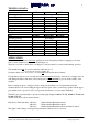
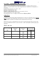
TECHNICAL DATA: Type Operating principle Rotor disc diameter Speed of PTO r/min No. of knives Power requirement min./max. Tree stem diameter, max. Chip length Weight Type Operating principle Rotor disc diameter Speed of PTO r/min No. of knives Power requirement Tree stem diameter, max.
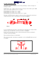
CONNECTION/MOUNTING The machine is designed for connection to a tractor three-point linkage or - with its own engine - for mounting on a trailer. The PTO shaft is 1 3/8" - 6 splines on the tractor side. On some types of tractor where a speed of 1000 r/min is used, the spline specification is 1 3/8" - 21 splines. TP 150 : Machine side: freewheel, 1 3/8" - 6 splines. TP 200 : Machine side: freewheel, 1 3/8" - 6 splines. TP 250: Machine side, freewheel and friction clutch, 1 3/4" - 6 splines.
OIL TYPES – TEMPERATURE AND VISCOSITY Mineral oils: We recommend the use of mineral-based hydraulic oil containing sufficient anti-wear additives, of a type that remains effective under marginal lubrication conditions at low temperatures, i.e. below 60°C. Normal working temperature from +30°C to +60°C. Minimum working temperature -30°C. Maximum working temperature +90°C. Within the working temperature range the viscosity should be 35-75 cSt. The least permissible viscosity is approx. 20 cSt.
KNIVES AND ANVILS It is not possible to determine the volume (m3) of chips that can be produced before it is necessary to sharpen the knives. This depends on chip length and especially on how much the raw wood is contaminated by sand, earth, etc. Before removing the knives the rotor must be locked by turning the locking pawl and inserting it in the appropriate hole in the rotor disc. With the pawl in locked position, each knife can be removed when in vertical position. To replace anvils, etc.
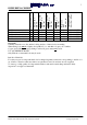
X 0 12 12 15 15 X X X X Tightening torque Max. [Nm / KPm] Unbrako type MK M12x50-12.9 DIN 7991 Unbrako type MK M12x45-12.9 DIN 7991 Flange nuts M12 DIN 6331-10 3/6 4/12 4/12 5/15 5/15 Unbrako type MK M12x55-12.9 DIN 7991 TP 150 TP 200 w/out sliver breaker TP 200 w/sliver breaker TP 250 w/out sliver breaker TP 250 w/sliver breaker M12x30-10.9 DIN 933 Bolts per knife / total KNIFE REPLACEMENT 110 Nm / 11 KPm 95 Nm / 9.5 KPm 95 Nm / 9.5 KPm 95 Nm / 9.5 KPm 95 Nm / 9.
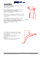
Grinding must be performed with a wet grindstone. See Figure 4. Never use a right-angle grinder for knives. When grinding knives, make sure that widths are identical in order to ensure good rotor balance. Knives must not be ground down to widths less than those given in the table. Min. Figure 5 TP 150 75 mm Figure 6 TP 200 75 mm Figure 7 TP 250 90 mm Figure 4 Figure 5 TP 150 Figure 6 TP 200 Figure 7 TP 250 Linddana A/S, Ølholm Bygade 70, DK-7160 Tørring, Instructions: TP 150-200-250 dated 05.12.
WOOD CHIPPING When starting the wood chipper make sure that the PTO shaft speed never exceeds 1000 r/min. (See tractor manual). For wood chippers equipped with “speed-up gear” the tractor PTO shaft speed must not exceed 540 r/min. Tractors with a PTO shaft speed of 1000 r/min must not be coupled to a “speed-up gear”. Turn the ejector spout and adjust the tilting section to give the correct discharge trajectory. Make sure no one is present in the discharge area.
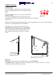
SAFETY HANDLE TP 150-200-250: The wood chipper is equipped with two hydraulic rollers, pressure-compensated flow valve, control valve and safety handle. The safety handle must be in its stop position (0) when the machine is started. After start, the handle must be placed in its mid position (A). The rollers will then turn and material will be drawn into the machine. See Figure 10.
SAFETY RULES General 1. 2. 3. 4. 5. 6. 7. 8. 9. 10. 11. 12. 13. The upper part of the machine must not be opened until the rotor/knives and tractor engine has come to a complete standstill. Always stop the machine and tractor before inspection, service or repair work is performed. After maintenance and/or repairs have been carried out, the machine must not be started until all bolts are tightened and all protection devices have been refitted.
PICTOGRAMS Read the instruction manual before use! Warning – rotating belts! Warning – rotor! Warning – rotating rollers! Safety distance! Ear and eye protection obligatory! Linddana A/S, Ølholm Bygade 70, DK-7160 Tørring, Instructions: TP 150-200-250 dated 05.12.
NOISE LEVEL The sound power level for the wood chippes has been measured during operation at 1000rpm with the chipper driven by a tractor. Test conditions Directive 2000/14/EC, 3. july 2000 EN ISO 3744, 1995 ISO 11094, of december 1993 ISO 4871, 19. of marts 1997 The guaranteed sound power level to be declared by the manufacturer according to directive 2000/14/EC for woodchipper is: TP 150 woodchipper, er 123 dB(A) re.1pW. TP 200 woodchipper, er 125 dB(A) re.1pW. TP 250 woodchipper, er 127 dB(A) re.1pW.
MAINTENANCE Before starting the machine, make sure all nuts and bolts are tight. Observe local authority requirements when disposing of old hydraulic oil and oil filters. When taking the machine out of service, drain off the hydraulic oil. Figure 13 Figure 14 applies to 200-250 series only Figure 15 Linddana A/S, Ølholm Bygade 70, DK-7160 Tørring, Instructions: TP 150-200-250 dated 05.12.
FAULT LOCATION TABLE Try to find the possible causes of faults before contacting the supplier. Problem Possible fault Rollers do not run satisfactorily Insufficient oil in hydraulic system. Flow valve screwed too far down. Wood fragments under lower roller. Remove lower roller cover plate and clean around roller. Flow valve to be screwed further up (open). Hydraulic pressure for control valve: TP 150-200 = max. 140 bar TP 250 = max. 170 bar Pressure relief valve in control valve needs cleaning.
ASSEMBLY AND REPAIR Hydraulics: When replacing hydraulic hoses, new flow and return hoses must be 3/8” R2AT. Hoses and fittings must have inch threads. A distributor authorised by us must perform replacement of the main shaft. When replacing main shaft bearings, cast steel bearing housings must be used. When replacing main shaft bearings, the main shaft must not be removed from the rotor disc. Bolts and nuts: When replacing bolts, use quality 8.8. All threads are metric.
MAINTENANCE SCHEDULE, TP 150-200-250 Interval=> PTO shaft lubrication1 Knife and anvil inspection2 Return filter, hydraulic pump3 All nuts and bolts4 Main bearings for rotor disc5 PTO shaft telescopic connection6 Roller shaft bearings7 Return filter for hydraulic pump8 Hydraulic oil change9 Anvil turn/replacement10 Wear plates on ejector blades11 Deflector in upper rotor housing12 Triangular and square strippers13 Grinding of flats on feed rollers14 Shell in rotor housing (TP 200-250 only)15 1 2 3 4 5
SPECIAL INSTRUCTIONS FOR TP 200 DH A C B Figur 16 Transport position A B Figur 17 Work position A C B Figur 18 Parking Linddana A/S, Ølholm Bygade 70, DK-7160 Tørring, Instructions: TP 150-200-250 dated 05.12.
SPECIAL INSTRUCTIONS FOR TP 150 PHM TP 150 PHM is a trailer-mounted wood chipper, i.e. a trailer on which the chipper is mounted complete with its own engine, and registered as a towed implement. Trailer can be linked to a vehicle fitted with an approved ball towing system. On hitching the trailer, the 7-pin plug and safety chain connections to the towing vehicle must be made, and the support leg must be lifted up. The handbrake must be off before driving off.
Following instruction covers general use of the engine. For further information: see the enclosed service and instruction manual from Lombardini or on www.lombardini.it. By registration for repair it is requested that you draw attention to the fact that it is a matter of warranty. This is to certify that a report is taken and that the parts are stored and tested according to the procedure laid down by the factory The engine is warranted for 2 years from the date of delivery.
TECNICAL DATA FOR LDW 1003: Number of cylinders Bore Stroke Volume Oil quantity Coolant quantity total (incl. motor) Fueltank kW @ 3600 o/min Max. Slope/in operation Max. Slope/very short-time 3 77,6 mm 75 mm 1028 cm3 2,4 liter 7 liter 24 liter 20,0 kW 25° 35° Check oil level before starting the engine. It has to be between Min. and Max. make sure that it is nearly at max. When toppingup the level is checked again.
B A D C F E G H A = Operation B = Oil lampe C = Temperature D = Charge control lampe E = Fuel indicator (not on TP150 PHM) F = Indicator for clogged air filter G = Glow plug indicator/preheat H = Key Starting: The key is turned clockwise and the glow plug indicator lights. Start the engine when the glow plug indicator has gone out Make sure that all warning lights are off when the engine is running. Do not actuate starter for more than 20 seconds at a time.
ENGINE MAINTANANCE OPERATIONS Frequency=> 10 125 250 500 1.000 2.500 5.
Probable cause! Obstructed fuel line Fuel filter clogged Air leaks in fuel system Clogged tank vent hole Injection sticking Injection pump valve sticking Injector not adjusted Faulty fuel feeding pump Hardened injection pump rack Extra fuel control level sticking Oil level too high Oil pressure sticking Oil pressure regulator not adjusted Worn oil pump Air into oil suction line Faulty pressure gauge or pressure switch Oil suction line clogged Discharged battery Cable connections uncertain or incorrect F
SPECIAL INSTRUCTIONS FOR TP 200 VHM TP 200 VHM is a trailer-mounted wood chipper, i.e. a trailer on which the chipper is mounted complete with its own engine, and registered as a towed implement. Trailer can be linked to a vehicle fitted with an approved ball towing system. On hitching the trailer, the 7-pin plug and safety chain connections to the towing vehicle must be made, and the support wheel must be pivoted up. The handbrake must be off before driving off.
SPECIAL INSTRUCTIONS FOR TP 250 DHM TP 250 DHM is a trailer-mounted, motor-driven slab cutter. The unit can be registered for inspection-free coupling and can be attached to any vehicle with a ball tow bar. The ball coupling head on the draw bar can be replaced by a shackle and pin set as an optional extra. Coupling height is adjustable from 380mm to 900mm.
Engaging the slab cutter. Cold start: Start motor. Set throttle handle so that the motor runs smoothly at low RPM. Allow motor to run for 30-60 seconds, depending on temperature. Engage cutter slowly and increase motor speed until it reaches maximum. Warm start: Follow same procedure as above. However, there is no need to allow the motor to warm up before engaging. Do not attempt to engage the cutter at full throttle. Stop: Remove all material from the cutter. Disengage the cutter.
1 2 3 4 5 6 7 Test draw bar brakes and ball head coupling Check draw bar set-up Test handbrake. Lubricate ball coupling Lubricate draw bar brake Tighten securing bar Tighten crown nut x x x x Every 2-3000 km at least once annually After approx. 500 km Approx. 50 km setting draw bar After all settings Before use Maintenance checklistBPW Special LongLasting Grease ECO-Li 91 After last journey Maintenance of draw bar.
HYDRAULICCHART, TP150 WITHOUT OVERLOAD PROTECTION HYDRAULICCHART, TP150 WITH OVERLOAD PROTECTION Linddana A/S, Ølholm Bygade 70, DK-7160 Tørring, Instructions: TP 150-200-250 dated 05.12.
HYDRAULICCHART, TP 200 WITHOUT OVERLOAD PROTECTION HYDRAULICCHART, TP 200 WITH OVERLOAD PROTECTION Linddana A/S, Ølholm Bygade 70, DK-7160 Tørring, Instructions: TP 150-200-250 dated 05.12.
HYDRAULICCHART, TP 250 WITHOUT OVERLOAD PROTECTION HYDRAULICCHART, TP 250 WITH OVERLOAD PROTECTION Linddana A/S, Ølholm Bygade 70, DK-7160 Tørring, Instructions: TP 150-200-250 dated 05.12.
HYDRAULICCHART, TP 250 WITH CRANE Linddana A/S, Ølholm Bygade 70, DK-7160 Tørring, Instructions: TP 150-200-250 dated 05.12.
USER´S MANUAL HC 960 CHIPPER CONTROL Häckslercontrol HC 960 Linddana A/S, Ølholm Bygade 70, DK-7160 Tørring, Instructions: TP 150-200-250 dated 05.12.
INTRODUCTION Chipper Control HC 960 has been designed to prevent chipper overload, therefore, eleminiating engine stalling. The use of HC 960 also removes the need for manual operation of the feeder. This is achieved by monitoring the cutting wheels RPM. If the speed drops below the manufacturers desired spec, the control stops the feeder. As the cutting wheel has regained its desired speed the control restarts the feeder, therefore allowing continious chipping.
PARAMETERS IN SEMI AUTOMATIC MODE Name Meaning Remarks L (ow) Minimum If the cutting wheel turns slower than the minimum speed, speed the feeder will be stopped in order to give the cutting wheel the chance to regain its normal speed . A value of f.e. P 10 means that the feeder will be stopped when the speed falls to a value which is 10% lower than the normal speed. Please note that there is no control if set to zero.
PARAMETERS IN FULLY AUTOMATIC MODE Name Meaning Remarks L (ow) Minimum If the cutting wheel turns slower than the minimum speed, speed the feeder will be stopped in order to give the cutting wheel the chance to regain its normal speed again. Please note that there is no control if set to zero. Valid values: 0-8000 rpm n (ormal) Normal speed Normal speed of the cutting wheel. At this speed the feeder starts. The value of the normal speed must be higher than the minimum speed. Valid values: L...
PROGRAMMING THE PARAMETERS The programming of the parameters is not possible while the engine is running. To enter the programming mode it is necessary to turn on the operating voltage while the S-button is pushed. You have to keep the S-button pushed until "L", toggling with the actual minimum speed appears in the display. Now all parameters can be programmed as shown in the table below: Push 2 0 It appears in the display: Remarks ehb, software version (f.e.
HOURMETERS The HC 960 is equipped with two hourmeters. During normal operation the speed is displayed. As soon as the cutting wheel stops, the total operating hours are displayed. This is indicated by “th“ (total hours), toggling between th and the actual value. By pushing the S-button once, the operating hours per day are displayed. This is indicated by the word “day“, toggling between day and the actual value.
GENERAL HINTS Interrupting the programming Did you interrupt the programming by turning off the operating voltage or by not pushing a button for longer than 60s, all changes which were made before the S-button was pushed will remain programmed. S-button has been pushed unintentionally Did you push the S-button too often while scrolling the parameters, you have to start again from the beginning. Turn off the key switch and turn it on again (while pushing the S-button) after a short time.