
User guide

CX-A4 INSTALLATION AND OPERATION MANUAL 4
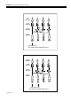
12 13 24
INPUT 1
1
2 3 4
POWER
AMPLIFIER
LEVEL
CONTROL
SOURCE
SWITCHES
INPUT
AMPLFIER
INPUT 2 INPUT 3 INPUT 4
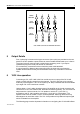
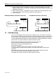
FOUR CHANNELS OPERATING AS INDEPENDENT AMPLIFIERS
1 2 3 4
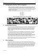
5 Output Details
Four 2-pole plug-in screw terminal type connectors (5mm pitch) are provided on the rear
panel for the four speaker outputs; these can accommodate flexible leads up to 2.50mm².
The plugs for these connectors are provided in the accessory pack. If you require
replacement plugs the Cloud part number is TP955188.
Do not make any connections to the unit with the power cable attached.
It is good practice to distance the output wiring from the input wiring and keep the
speaker wires twisted until they are terminated to reduce any cross-talk to a minimum
level.
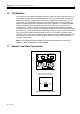
6 100V Line operation
Connecting a CXL-100T 100W 100V-line module across an output of the CX-A4 will
obtain a 100W 100V-line output from that channel. The CXL-100T has to be mounted
externally of the amplifier. A 2U 19" rack panel (CXL-800) is available that accommodates
up to eight CXL-100T transformer modules.
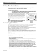
Using at least 1.5 mm² cable, wire the output of the amplifier to the 2 pole connector and
connect to the CXL-100T ‘AMPLIFIER’ terminations observing polarity. The 70V/100V-line
output uses the 3 pole connector; for 70V speakers, use the 0V (-) and 70V (+)
terminations and for 100V speakers use the 0V (-) and 100V (+) terminations. The
speaker cable must be at least 0.75mm², double insulated. With long distances it may
advantageous to use thicker cable. The CXL-100Tprovides a fully balanced output signal
which is isolated from the amplifier.
The following page contains important information on configuring the CX-A4’s 65Hz filters
15-01-09 V10.0