
Installation Guide
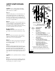

#1 Snap Latch
AUTO-LATCH LOCK ASSEMBLY
INSTRUCTIONS
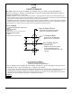
Step 1
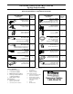
Using the template provided on page 6, drill three
holes through the garage door. The template should
be placed at a location nearest the center of the door
on the second section. (FIG. 1)
NOTE: To assure easy installation the holes must be
drilled straight. (Not at an angle.)
Step 2
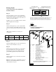
Slide the rubber gasket (8) over the outside handle
(1), then insert the outside handle and the two lock
spacers (7)* into the holes in the lock section. (FIG.
2)
*Please refer to table below for lock spacer
configuration.
Door
Style
Uninsulated
1 3/8”
Insulated
2”
Insulated
2” Pinch
Resistant
Spacer 2” Plastic
1-3/8”
Plastic
None
1-7/8”
Plastic
Step 3
Attach the backing plate (2) to the outside handle (1)
using two #10 x 24 machine screws (3).
Step 4
Slide the inside release handle (4) over the shaft of
the outside handle and secure in place using the
Tinnerman nut (5). Be sure the Tinnerman nut is
pressed firmly against the inside release handle.
Step 5
Slide the vinyl sleeve (6) over the arm of the inside
release handle.
Note: The Spring Latches, Striker Plates and Lock
Cables are to be assembled after the door and all
other hardware are in place.
Center Width of Door
Template Placement (See Fig 4)
Note: Panel configuration may differ depending on the width of the door.
If door has an odd number of panels lock to be installed off center.
FIGURE 1
Center of Door in Height
Remarque:Laconfigurationdupanneaupeutdifférerselonlalargeurdelaporte.
Silaportecomporteunnombreimpairdepanneaux,leverrouseradécentré.
Centredelalargeurdelaporte
Emplacementdugabarit(voirfig4)
Centredelahauteurdelaporte
Centrodelapuertacon
respectoalancho
Colocacióndelaplantilla(Refiéraseala
figura4).
FIGURA 1
#1 Snap Latch
Fermetureàenclenchementn°1
CerraduraapresiónNº1
NO.
QTY DESCRIPTION
11
21
41
Key blanks are available through Clopay.
Rubber Gasket
Vinyl Sleeve
Tinnerman Nut
Inside Release Handle
#10-24 Machine Screws
Backing Plate
Outside “T” Handle
½” DIA (TYP)
FIGURE 2
FIGURA 2
½ poDIA(TYP)
½”DIÁM .(TIP )
QUANTITÉ
DESCRIPTION
Nº
CANT.
N°
DESCRIPCIÓN
Poignéeextérieureen« T»
Manijaexternaen“T”
Plaqued'appui
Placadesujeció n
32
Visà métauxn°10‐24
T o rn illo s parametalesNº10‐24
Poignéeded év e r r o uilla g eintérieu re
Manijadeli b e r a c i ó n interior
51
ÉcrouTinnerman
TuercaTinnerman
61
Manchonenvinyle
Manguitodev inilo
72
Spacer Tubes (As Needed)
Tubesespaceurs(au besoin)
Tubosespaciadores(s egú nse anecesario)
81
Tampondecaoutchouc
Empaquetaduradegom a
Ilestpo s s ible deseprocurerdesclésbrutesauprèsdeClopay.
Clopaytien edisponiblesllav e s enbruto.