
Instructions / Assembly


2
2
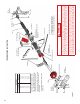
Fig. TOR-2
Locking Pliers
Double Spring Setup Shown
For Both Single Spring and Double Spring Setups:
Red Winding Cone Spring – Mount on Left Side
Black Winding Cone Spring – Mount on Right Side
3/8" Flange Nut
3/8" Hex Head Bolt
3/8" x 3/4"
Hex Head Bolts
3/8" x 3/4"
Carriage Bolt
(2) Places
3/8"
Flange Nut
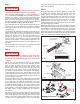
Some springs will have the wire diameter, spring
diameter, spring length, direction of wind, and a
winding stripe stenciled on the coils. If the springs
are stenciled, the number of spring turns can be
counted using the winding stripe. If not, the number
of spring turns can be counted by drawing a chalk
line on the spring.
* In low headroom applications subtract 1/2 spring
turn from chart.
2
F
ig. TOR-2
s
L
oc
ki
ng
Pli
er
s
D
ouble
S
pring
S
etup
S
how
n
F
or Both Single Spring and Double Spring Setups:
R
e
d
W
inding
C
one
S
pring – Mount on Le
f
t
S
ide
Bla
ck
W
inding
C
one
S
pring – Mount on Right
S
ide
3
/8" Flan
g
e Nu
t
3/8
" H
e
x H
ea
d
B
o
lt
3/8
" x
3/
4
"
He
x
Head
Bol
t
s
3/8
" x
3/
4
"
Carria
g
e Bolt
(
2
)
Place
s
3/8"
Fl
ange
N
ut
S
ome springs will have the wire diamete
r
,
spr
i
n
g
diamete
r
, spring length, direction of wind, and a
windin
g
stripe stenciled on the coils. If the sprin
g
s
a
re stenciled, the number of spring turns can be
counted usin
g
the windin
g
stripe. If not, the number
o
f sprin
g
turns can be counted b
y
drawin
g
a chal
k
l
ine on the sprin
g
.
* In low headroom applications subtract 1/2 sprin
g
turn from chart
.
Nylon Center Bearing
(One Side Only) Tapered Side Goes
in Spring Cone
Cable
RH End
Bearing Plate
RH
Drum (Black)
Winding Cone
Black RH
Line
Center Bearing Plate
Spring Warning
Tag
Warning
Tag
Wood Anchor Pad
(See Warning Below)
Winding Bar
(See Warning Below)
Winding Cone Red LH
3:00 Position
End Cable and Stop Button
5/16" x 1-5/8"
Lag Screw
Cable
Winding Chart
Door Height
6'0"
6'3"
6'6"
6'9"
7'0"
7'3"
7'6"
7'9"
8'0"
6.75
7.00
7.25
7.50
7.75
8.00
8.25
8.50
8.75
Spring Turns*
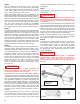
TORSION SPRING INSTALLATION
WARNING
ALWAYS USE GOOD QUALITY, SNUG FITTING, CONSTANT DIAMETER, SOLID STEEL WINDING
BARS WHEN WINDING OR ADJUSTING SPRINGS. THE USE OF ANY OTHER OBJECT CAN RESULT
IN SEVERE INJURY. WHEN WINDING THE SPRINGS, THE WINDING BAR MUST BE INSERTED INTO
THE FULL DEPTH OF THE HOLES IN THE WINDING CONE. KEEP A FIRM GRIP ON THE WINDING
BARS AT ALL TIMES. USE A STURDY LADDER AND STAND TO THE SIDE OF THE WINDING BARS.
IF YOUR DOOR HAS A TORSION SPRING ASSEMBLY, YOU MUST MAKE SURE THAT THE WOOD
ANCHOR PAD (SEE DRAWING) IS FIRMLY ATTACHED TO THE GARAGE WALL AS DESCRIBED IN THE
DETAILED INSTRUCTIONS ON THE NEXT PAGE. FAILURE TO SECURELY ATTACH THE ANCHOR PAD
COULD ALLOW THE SPRINGS TO VIOLENTLY PULL AWAY FROM THE GARAGE WALL, AND COULD
RESULT IN SEVERE INJURY AND/OR PROPERTY DAMAGE. IN NO CASE SHOULD NAILS BE USED.