
Instructions / Assembly


4
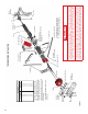
Step 4
With an assistant, lift the complete torsion spring tube
assembly and slide the ends of the tube into the bearing
on the end bearing plates. With the tube level, mount the
center bearing plate to the center anchor pad using (2)
5/16" x 1-5/8" long lag, red-coated screws.
NOTE: Red-headed fasteners must be installed for the
attachment of center bearing plate to indicate this part will be
under extreme tension once spring is wound (Fig. TOR - 5).
Before mounting the center bearing plate, drill (2) 3/16" pilot
holes for the lag screws. These pilot holes must be no closer
than 1-1/2" from the sides and ends of the wood anchor
pad. The center bearing plate resists the considerable
counter torque of the springs. This wood anchor pad must
be installed to the frame of the garage as stated in Step 1.
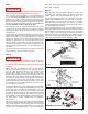
Step 5
The cable that is attached to each bottom bracket is brought
up between the wall and roller shafts to the cable drum. This
cable is placed in the notch on the cable drum. Turning the
cable drum and sliding it up tight against the end bearing
plate removes the cable slack. Make sure the cable follows
the grooves in the cable drum. The set screws on the cable
drum should be tightened with a 3/8" box wrench while
holding the cable taut. Locking pliers clamped to the torsion
spring tube maintain tension on the cable (Fig. TOR-2). This
procedure should be repeated on the opposite side.
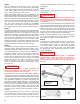
Step 6
The following instructions apply to both galvanized and oil-
tempered springs. Oil-tempered springs are dark in color.
Galvanized springs have a bright zinc (silver-colored) coating.
The stenciled description can be used as a straight line to
indicate the number of turns on the spring(s). If there is no
straight line present, make one with a piece of chalk. After
inserting the two winding bars all the way into the winding
cone, wind the springs 1/4 turn at a time in an upward
direction as shown in Fig. TOR-5. The number of turns is
shown in the table in Fig. TOR-2. The tail of the torsion
spring coil points in the direction that the spring is wound
(Fig. TOR-5A).
WARNING
NEVER use screwdrivers or other substitutes for
winding bars! Stand to the side of bars. Be sure to
insert the bars all the way into the hole.
TIP: The balance of the door may differ slightly depending
on whether galvanized or oil-tempered springs are provided.
If galvanized springs are provided, the initial balance of the
door may appear slightly “hot” (door drifts upward) with the
turns specied in the table in Fig. TOR-2. The spring(s) will
self adjust and relax slightly, resulting in a balanced door
within a few weeks of normal operation. To accelerate this
effect at the time of installation, proceed to wind the spring
two extra full turns past the number of turns shown in the
table in Fig. TOR-2. Next, carefully unwind the two extra
full turns until the spring(s) equal the number of turns in
the table.
Secure each spring with the set screws on the winding
cone. (Caution: Set screws should be turned from 3/4 to
one full turn after they have made contact with the tube.)
On doors with two torsion springs, each torsion spring
should be wound the same number of turns. Remove the
locking pliers.
Step 7
Unlock the door, slowly raise the door and prop it about
halfway open.
WARNING
This is the rst time the new door is being opened. If the
tracks are not correctly aligned or the back hangers are
not strong enough, the door may fall. Proceed slowly
and carefully.
Check to be sure the horizontal tracks are parallel with each
side of the door. Make sure all the lag screws are securely
fastened. With the door about halfway open, make sure the
rollers do not come out of the top brackets more than about
1/2 inch. If adjustment of the rear track hanger is necessary,
the door must be locked in the closed position because the
weight of the door is supported by the rear hangers.
NOTE: If the torsion springs do not increase in tension as
the 1/4 turns are added to the springs, then you probably
have the torsion springs reversed. (See Step 2.)
Step 8
To adjust torsion spring tension, the door is locked in the
down position. With locking pliers clamped on the torsion
tube, winding bars are used to wind the springs tighter
to increase tension. Tension is reduced by removing
turns. When two springs are used, both sides should
be adjusted the same. Adjustments should be made in
1/4 turn increments.
WARNING
NEVER adjust center bearing plate or red-headed
fasteners after springs are wound. Be prepared to
handle a strong force when reducing tension on a
torsion spring. Use winding bars only, and stand to
the side.
Fig. TOR-5
Fig. TOR-5A
Red Head
5/16" x 1-5/8"
Lag Screw
Use only the specified
winding bars. Never
use substitutes.
1/2" Dia., 18" Long
Solid Cold Rolled Steel
Winding Bars
Fig. TOR-5
Fig. TOR-5A
Red Head
5/16" x 1-5/8"
Lag Screw
Use only the specified
winding bars. Never
use substitutes.
1/2" Dia., 18" Long
Solid Cold Rolled Steel
Winding Bars
SUP_0137170-R05-0614