
Installation Guide

3
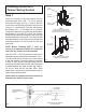
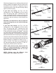
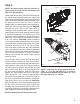
Step 1
Attach the bracket to the ag bracket and the
horizontal angle with a 3/8" - 16 x 3/4" carriage
bolt and 3/8" ange nut (Fig. 1, View A). Be sure
to orient the carriage bolt and ange nut as shown
in Figure 1, views A and B. Remove and reattach
the existing 3/8" - 16 carriage bolt as required.
The bracket should be up against the jamb and the
ag bracket. If your door is 2" thick, the carriage
bolt should be fastened through the slot in the ag
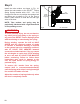
bracket farthest from the jamb. If you have double
track low headroom, see Figure 2 for carriage bolt
mounting locations. Do this for both the left and
right sides.
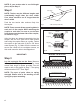
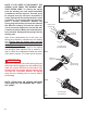
NOTE: Before installing 5/16" x 1-5/8" lag
screws, it is important to drill 3/16" pilot holes
where the lag screws are to be attached.
Use two 5/16" x 1-5/8" lag screws to connect the
brackets securely to the jamb or the header. (Fig. 1,
View B) Install the lag screws in the slots closest
to the ag bracket if possible. Before proceeding
to Step 2, make sure the carriage bolt(s) and the
lag screws are fastened securely and the bracket
is seated against the jamb and the ag bracket.
Do this for both the left and right sides. Solid
attachment is critical since these brackets will be
under strong spring tension.
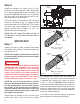
NOTE: Refer to standard instruction manual to
determine the radius of your track.
Installing the EZ-SET
®
Torsion Spring System
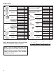
Fig. 1
Flag
Bracket
Jamb
Bracket
Horizontal
Angle
VIEW A
2" THICK DOOR (LEFT SIDE SHOWN)
12" RADIUS TRACK, USING SLOTS 1 & 4
15" RADIUS TRACK, USES TOP TWO SLOTS
Existing
3/8" Flange Nut
3/8" - 16 x 3/4"
Carriage Bolt
Bracket
Lag Screw
Jamb
15" Radius
Track Slots
Lag Screw
VIEW B
2" THICK DOOR (LEFT SIDE SHOWN)
12" RADIUS TRACK, USING SLOT 1
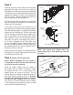
Fig. 2
Flag Bracket
Insert Carriage Bolts from
Opposite Side Similar
to Fig. 1B
Bracket
Low Headroom
Starter Angle
Horizontal Tracks
DOUBLE TRACK LOW HEADROOM
(LEFT SIDE SHOWN)