
Installation Guide

4
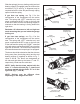
NOTE: If your torsion tube is one full-length
piece, skip to Step 3.
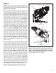
Step 2
NOTE: Torsion may be different lengths and
considerably longer than the door width.
If so, tubes should be cut 9" longer than the
door's width.
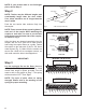
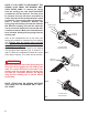
Push the two torsion tube sections rmly into
the coupler.
NOTE: There are sets of two opposing holes in
each end of the coupler. When attaching the
coupler to each tube, be sure to use the two
holes that are on the same side of the coupler,
as shown in Fig. 3.
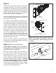
After the tubes are inserted completely into the
coupler, drill one 3/16" pilot hole in each torsion
tube using the coupler holes as a guide. Fasten
the coupler to the tube with (2) #14 x 5/8" sheet
metal screws (Fig. 3). Make sure the screws are
secure. Be careful not to overtighten screws, as
this could cause the hole to be stripped out.
IMPORTANT!
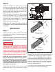
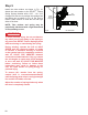
Step 3
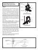
Lay the spring(s) at on the oor. Measure
the length of each spring as shown in Fig. 4 and
record each length in space provided. You will
need to refer to this length in Step 7. The spring
will be stenciled “LEFT” and “Right”.
NOTE: The spot of paint refers to spring
strength. Please refer to the wording on the
spring for proper mounting.
Fig. 3 TUBE COUPLER (IF SUPPLIED)
Tube Coupler
Torsion Tubes
#14 x 5/8" Sheet
Metal Screw
Fig. 4
Left Spring
Right Spring
Fig. 4A DETAIL VIEW
Set Cone
Spring Plug
Spring Plug
End of
Spring
Right Side Spring Length
(RECORD LENGTH HERE)
RIGHT
LEFT
MEASURE ON THE FLOOR
End of
Spring
End of
Spring
End of
Spring
(RECORD LENGTH HERE)
Left Side Spring Length