
Installation Guide

8
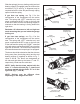
Step 6
Install the included 1/4" insert bit (or a 7/16"
socket) in a medium duty drill: 1000 – 2500 RPM,
(2 – 4 amps) variable-speed and reversible. Set
the drill to FORWARD (clockwise as you point the
drill away from you). Keep this drill and a 3/16"
hex key handy for Steps 8 and 9.
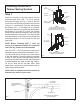
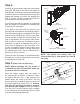
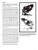
To turn the stripe on the spring so that it is facing
toward you as shown in Fig. 11, engage the drill
at half speed with the 1/4" insert bit (7/16" socket)
into drive shaft of the winding unit to rotate the
spring until the stripe is facing you (Fig. 11).
Remove drill and bit completely.
NOTE: The 1/4" insert bit shown in Fig. 11
is secured in a drill chuck, but the drill is
not shown.
IMPORTANT!
Step 7
Holding the tube in place, measure and adjust
the length of the spring to match the length you
recorded in Fig. 4.
NOTE: This length should not be less than the
recorded length and should not exceed length
by more than 1/2".
WARNING
DO NOT OVERSTRETCH SPRING(S) BEFORE
TIGHTENING SET SCREWS. Over-stretching
the springs could cause the loss of spring
tension and possibly allow the door to fall. The
length of the spring on the shaft should NOT
exceed the relaxed spring length recorded in
Step 3 on page 4 of the EZ-SET
®
Torsion Spring
System Instructions by more than 1/2" max.
NOTE: Be sure to hold the tube in position
after you have tightened the spring set screws.
Use the locking pliers on both ends (against
the outside of the bracket with the drum) to
eliminate side-to-side movement of tube. Any
sliding of the tube from this point on will affect
the length of the springs.
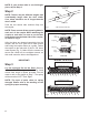
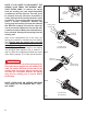
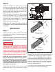
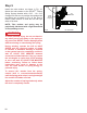
Tighten both set screws in the set cone to the
torsion tube. Use a 3/4" wrench if the springs
are supplied with square head set screws as
shown in Fig. 12, view A. Use a 3/16" hex wrench
if supplied with internal set screws as shown
in Fig. 12, view B. CAUTION: When resistance
is encountered while tightening the set screw, the
screw has made contact with the tube. Set screws
should be turned from 3/4" to one full turn after
they have made contact with the tube. Additional
turns may damage the tube.
If you have a door with two springs, repeat the
above procedure for the right side spring.
Stripe
Fig. 11
Clockwise
Winding
Direction
Fig. 12
External Set
Screws
Torsion
Tube
Set Cone
Torsion Spring
Internal Set
Screws
Set Cone
Torsion
Tube
Torsion Spring
VIEW A – Set Cone Shown with
Square Head Set Screws
VIEW B – Set Cone Shown with
Internal Set Screws