
User manual

VB7009
VB7009VB7009
VB7009
User Manual
User ManualUser Manual
User Manual
14
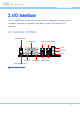
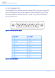
2.1.5. RJ45 LAN port: Gigabit Ethernet
The two integrated 8-pin Gigabit Ethernet ports are using an 8 Position 8
Contact (8P8C) receptacle connector (commonly referred to as RJ45). The
Gigabit Ethernet ports are controlled by VIA Gigabit Ethernet controller. The
pinout of the Gigabit Ethernet port is shown below.
Pin
PinPin
Pin
Signal
SignalSignal
Signal
1 Signal pair 1+
2 Signal pair 1-
3 Signal pair 2+
4 Signal pair 3+
5 Signal pair 3-
6 Signal pair 2-
7 Signal pair 4+
8 Signal pair 4-
Table
Table Table
Table 5
55
5: Gigabit Ethernet port pinout
: Gigabit Ethernet port pinout: Gigabit Ethernet port pinout
: Gigabit Ethernet port pinout
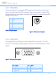
Figure
Figure Figure
Figure 10
1010
10: Gigabit Ethernet port pinout diagram
: Gigabit Ethernet port pinout diagram: Gigabit Ethernet port pinout diagram
: Gigabit Ethernet port pinout diagram
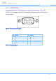
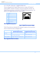
The RJ-45 port has two individual LED indicators located on the front side to
show its Active/Link status and Speed status.
Link LED
Link LEDLink LED
Link LED
(Left LED on RJ
(Left LED on RJ(Left LED on RJ
(Left LED on RJ-
--
-45 connector)
45 connector)45 connector)
45 connector)
Active LED
Active LEDActive LED
Active LED
(Right LED on RJ
(Right LED on RJ(Right LED on RJ
(Right LED on RJ-
--
-45 connector)
45 connector)45 connector)
45 connector)
Link Off Off Off
Speed_10Mbit The LED is always On and flashing in
colors Green and Orange
Flash in Yellow color
Speed_100Mbit The LED is always On in Green color Flash in Yellow color
Speed_1000Mbit The LED is always On in Orange color Flash in Yellow color
Table
Table Table
Table 6
66
6: Gigabit Ethernet LED color de
: Gigabit Ethernet LED color de: Gigabit Ethernet LED color de
: Gigabit Ethernet LED color definition
finitionfinition
finition