
User manual

VB7009
VB7009VB7009
VB7009
User Manual
User ManualUser Manual
User Manual
22
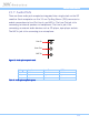
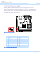
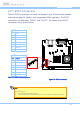
2.2.6. CPU and System Fan Connectors
There are two fan connectors on board: one for the CPU and one for the
chassis. The fan connector for the CPU is labeled as “CPUFAN1” and the fan
connector for the system is labeled as “SYSFAN1”. The fans provide variable
fan speeds controlled by the BIOS. The pinout of the fan connectors is shown
below.
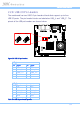
CPUFAN1
1
SYSFAN1
1
Figure
Figure Figure
Figure 18
1818
18: Fan connectors
: Fan connectors: Fan connectors
: Fan connectors
CPU fan
CPU fanCPU fan
CPU fan (C
(C (C
(CPUFAN1
PUFAN1PUFAN1
PUFAN1)
))
)
Pin
PinPin
Pin
Signal
SignalSignal
Signal
1 F_IO2 / Fan speed detection
2 F_PWM2 / Fan speed control
3 GND
System fan (SYSFAN1)
System fan (SYSFAN1)System fan (SYSFAN1)
System fan (SYSFAN1)
Pin
PinPin
Pin
Signal
SignalSignal
Signal
1 F_IO1 / Fan speed detection
2 F_PWM1 / Fan speed control
3 GND
Table
Table Table
Table 14
1414
14: Fan connector pinouts
: Fan connector pinouts: Fan connector pinouts
: Fan connector pinouts