CX-A200 Amplifier Installation & User Guide Cloud Electronics Limited 140 Staniforth Road, Sheffield, S9 3HF England Tel +44 (0)114 244 7051 Fax +44 (0)114 242 5462 e-mail info@cloud.co.uk web site http://www.cloud.co.
CX-A200 INSTALLATION AND OPERATION MANUAL 1 CX-A200 Amplifier Installation and operation manual Contents Section Page 1 Safety Notes...............................................................................2 2 General Description....................................................................2 3 Installation ..................................................................................2 4 Input Facilities ............................................................................
CX-A200 INSTALLATION AND OPERATION MANUAL 1 2 Safety Notes The CX-A200 contains several PCB mounted jumpers which can be set to provide the desired configuration for a specific venue or installation. These adjustments should be performed by a technically qualified person who understands the hazards associated with mains operated equipment. Do not remove the top panel unless you are qualified to do so.
CX-A200 INSTALLATION AND OPERATION MANUAL 4 3 Input Facilities All four inputs are balanced and use 3 pin XLR type connectors. All inputs are wired to the standard convention of pin 1 ground, pin 2 in-phase, pin 3 reverse phase, with the shell of the connector connected to the chassis.
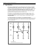
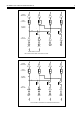
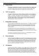
CX-A200 INSTALLATION AND OPERATION MANUAL POWER AMPLIFIER 4 1 2 3 4 LEVEL CONTROL SOURCE JUMPERS INPUT AMPLFIER 1 1 2 2 3 4 1 2 INPUT 1 INPUT 2 3 4 3 4 FROM STEREO SOURCE TWO STEREO PAIRS FROM ONE STEREO SOURCE POWER AMPLIFIER 1 2 LEVEL CONTROL SOURCE JUMPERS INPUT AMPLFIER 1 1 2 2 3 4 1 2 3 4 INPUT 1 INPUT 2 INPUT 3 INPUT 4 FOUR CHANNELS OPERATING AS INDEPENDENT AMPLIFIERS
CX-A200 INSTALLATION AND OPERATION MANUAL 5 5 Output Details Binding posts are provided on the rear panel for the four speaker outputs and these can accommodate flexible leads up to 2.50mm². The output connector is not compatible with 4mm 'Banana' plugs. Do not make any connections to the unit with the power cable attached. It is good practice to distance the output wiring from the input wiring.
CX-A200 INSTALLATION AND OPERATION MANUAL 6 circuitry uses the industry standard 'Thats 2150A' VCA providing very low distortion and up to 90dB attenuation. The VCA module can be wired to provide muting by using an auxiliary relay connected to a fire alarm control panel. See section 11 'Remote Level Plate Connections' for wiring details. 10 Fitting a VCA Module Remove the power cable before commencing.
CX-A200 INSTALLATION AND OPERATION MANUAL 12 7 Field Servicing The CX-A200 is ruggedly built and uses proven reliable circuitry. It requires no more than the occasional removal of any dust that may have built up inside the unit as a result of the forced cooling. In the unlikely event of failure, the power amplifier module (4 channels) complete with power supply components and input circuitry can be replaced without special tools and is available as a tested replacement assembly complete with heatsink.
CX-A200 INSTALLATION AND OPERATION MANUAL 8 This product conforms to the following European Standards EN 50081-1: 1992 EN 50082-1: 1992 EN 60065 : 1994 SAFETY CONSIDERATIONS CAUTION - MAINS FUSE TO REDUCE THE RISK OF FIRE REPLACE THE MAINS FUSE ONLY WITH THE SAME TYPE, WHICH MUST BE A CLASS 3, 240 VOLT, TIME DELAY TYPE, RATED AT 3.15A WHERE THE MAINS INPUT VOLTAGE IS SET TO 230 Volts ± 5% AC. FOR A MAINS VOLTAGE OF 115 Volts ± 5% AC. THE FUSE SHOULD BE RATED AT 6.3A THE FUSE BODY SIZE IS 20mm x 5mm.