CX-A6 Amplifier Installation & User Guide V8.0 Cloud Electronics Limited 140 Staniforth Road, Sheffield, S9 3HF England Tel + 44 (0) 114 244 7051 Fax + 44 (0) 114 242 5462 E-mail info@cloud.co.uk Web site http://www.cloud.co.
1 CX-A6 INSTALLATION AND OPERATION MANUAL Model CX-A6 Multi-Channel Amplifier Installation and operation manual Contents Section 15-07-02 V8 Page 1 General Description ...................................................................2 2 Installation ..................................................................................2 3 Input Facilities ............................................................................2 4 Output Details ..................................................
CX-A6 INSTALLATION AND OPERATION MANUAL 1 2 Safety Notes • Do not expose the unit to water or moisture • Do not expose the unit to naked flames. • Do not block or restrict any air vent • Do not operate the unit in ambient temperatures above 35oC • Do not touch any part or terminal carrying the hazardous live symbol ( ) while power is supplied to the unit. • Do not perform any internal adjustments unless you are qualified to do so and fully understand the hazards associated with mains operated equipment.
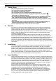
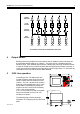
3 CX-A6 INSTALLATION AND OPERATION MANUAL POWER AMPLIFIER 1 2 3 4 5 6 LEVEL CONTROL SOURCE SWITCHES INPUT AMPLFIER 1 2 1 1 3 2 2 4 3 1 5 4 2 6 5 6 INPUT 1 FROM MONO SOURCE POWER AMPLIFIER 1 SIX CHANNELS DRIVEN FROM ONE MONO SOURCE 2 3 4 5 6 LEVEL CONTROL SOURCE SWITCHES INPUT AMPLFIER 1 2 1 2 INPUT 1 INPUT 2 FROM STEREO SOURCE 15-07-02 V8 1 3 3 2 4 4 1 5 5 THREE STEREO PAIRS DRIVEN FROM ONE STEREO SOURCE 2 6 6
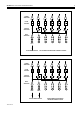
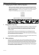
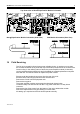
4 CX-A6 INSTALLATION AND OPERATION MANUAL POWER AMPLIFIER 1 2 3 4 5 6 LEVEL CONTROL SOURCE SWITCHES 1 INPUT AMPLFIER 2 1 3 2 4 1 5 2 6 1 2 3 4 5 6 INPUT 1 INPUT 2 INPUT 3 INPUT 4 INPUT 5 INPUT 6 SIX CHANNELS OPERATING AS INDEPENDENT AMPLIFIERS 4 Output Details Binding posts are provided on the rear panel for the six speaker outputs and these can accommodate flexible leads up to 2.50mm². The posts are not compatible with 4mm 'Banana' plugs.
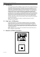
5 CX-A6 INSTALLATION AND OPERATION MANUAL 6 Configuring the CX-A6 for 100V-line Operation When a CXL-100 is connected to a channel of the CX-A6, that channel must have its 65Hz high-pass filter operational. Without this filter operational, the presence of high input levels at frequencies below 50Hz may result in transformer saturation causing the amplifiers VI limiter to operate. The filter can be switched on by moving the relevant jumper to the ‘IN’ position.
6 CX-A6 INSTALLATION AND OPERATION MANUAL 9 VCA Modules A two-channel VCA module is available as a plug-in option for the CX-A6 (see section 13 for installation details) and can be used with either one or two control plates. The unit can operate two channels independently or switched to provide stereo attenuation via one control plate. For independent operation, the switch should be in the 'solo' position (in), with the remote level controls connected to both 3 pin connectors.
CX-A6 INSTALLATION AND OPERATION MANUAL 12 7 Bose Equalisation Modules Each channel on the CX-A6 can have Bose equalisation so that its output will be compensated correctly for a wide range of 100Vline Bose speakers. The Bose equalisation module for the CXA6 is a two-channel device; the CX-A6 requires three modules to be installed to allow compensation on every channel of the amplifier.
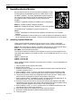
8 CX-A6 INSTALLATION AND OPERATION MANUAL Top Down View of Bose Equalisation Module Orientation Bose Equalisation Module Orientation (Side View) 14 VCA Module Orientation (Side View) Field Servicing The CX-A6 is ruggedly built and uses proven reliable circuitry. It requires no more than the occasional removal of any dust that may have built up inside the unit as a result of the forced cooling.
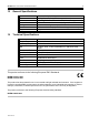
9 CX-A6 INSTALLATION AND OPERATION MANUAL 15 General Specifications Inputs Outputs Protection Status Indicators Cooling Dimensions Weight 16 Balanced via 3 pin XLR type connector. Binding Posts for flexible cables up to 2.5mm² VI limiting, DC offset, Thermal and Switch-on Delay LED indicators on each channel for Signal, Peak & Protect Force cooled using a two speed DC fan. 482.6mm x 88.0mm (2U) x 325.
CX-A6 INSTALLATION AND OPERATION MANUAL 10 Safety Considerations and Information The unit must be earthed. Ensure that the mains power supply provides an effective earth connection using a three wire termination.