CX233 Zoner Mixer Installation & User Guide Cloud Electronics Limited 140 Staniforth Road, Sheffield, S9 3HF England Tel +44 (0)114 244 7051 Fax +44 (0)114 242 5462 e-mail info@cloud.co.uk web site http://www.cloud.co.
CX233 INSTALLATION AND OPERATION MANUAL 1 CX233 Zone Mixer Installation and operation manual Contents Section Page 1 General description ....................................................................2 2 Music inputs ...............................................................................2 3 2.01 Music inputs.....................................................................2 2.02 Gain Control.....................................................................2 2.
2 1 CX233 INSTALLATION AND OPERATION MANUAL General Description The CX233 is a versatile multi-source mixer/zoner that can be used with confidence as part of a professional sound system. The impressive performance and flexible routing options together with the remote level control facility make it suitable for a wide range of applications.
CX233 INSTALLATION AND OPERATION MANUAL 3.02 3 Gain Control Pre-set gain controls are provide adjacent to the respective XLR input connector. The gain can be adjusted from 6dB to 60dB of gain. The wide range of gain allows direct connection of high output devices such as radio microphones without the need for input attenuators. A high overload margin of 20dB is maintained at all gain settings. 3.
4 CX233 INSTALLATION AND OPERATION MANUAL 4.03 Stereo/Mono Operation All CX233's leave the factory configured for stereo operation. By configuring circuit jumpers on the upper PCB each output zone can be configured to operate in the mono mode. When operating in the mono mode, the output signal is present on both left and right output connectors and either, or both may be used. 5 VCA Modules 5.
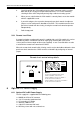
CX233 INSTALLATION AND OPERATION MANUAL 5.03 5 4. Carefully position the VCA module on to the 10 pin connector making sure that both rows of pins engage in the pcb mounted socket. This can be verified by checking that the 3mm fixing hole perfectly aligns with the mounting spacer. 5. When you are satisfied that the VCA module is correctly fitted, secure the module with the supplied M3 screw. 6.
6 CX233 INSTALLATION AND OPERATION MANUAL 6.02 Fitting of DC to DC power supply 1. 2. 3. 4. 5. 6 7. 8. 9. 7 Disconnect the CX233 from the mains power Remove the top and bottom panels Fit the two spade terminals on to the PCB. It is clearly marked Red+ve, Black-ve. Then solder them in place Fit the fuse holder to the PCB in the location marked F1. Solder this in place then fit the T800mA fuse. Fit the NMXD2415 to the pcb, then solder in place. All the soldered joints should be cut flush with the joint.
CX233 INSTALLATION AND OPERATION MANUAL 10 7 Unbalanced Mode If the zone outputs are required to operate in the unbalanced mode, it is suggested that the unused pin of the XLR connector is not connected. The nominal output signal in this mode is -6dBu and a small amount of extra gain may be required. 11 Technical Specifications Music Channels Frequency Response ±0.5db 20Hz/20kHz Distortion <0.
8 CX233 INSTALLATION AND OPERATION MANUAL General Specifications Power Consumption 25VA Power Requirements 115V ± 5% or 230V ± 5% Fuse Ratings Power T250mA at 115V Power T125mA at 230V Battery T800mA (internal) Width 482.6mm (rack) 432.0mm (free standing) Height 88.0mm (2U) Depth 192.00mm Weight 5.