
User guide


CX261 User Manual v1.0 9
9
Microphone Inputs
Two microphone inputs are provided; the microphone pre-
ampliers are an electronically balanced, transformer-less
design congured for optimum low noise performance. The
input impedance is greater than 2 kΩ and is suitable for
microphones in the 200 Ω to 600 Ω range.
15 V phantom power is available on either or both mic
inputs for powering condenser mics, and is activated by
setting internal jumpers J1 and J2 (for mic inputs 1 and 2
respectively) to the ON position. See page 15 for location
of jumpers. Care should be taken to ensure that phantom
power is activated only when the microphone connected to
the input requires external phantom power; damage to the
microphone may result otherwise.
Mic 1 input may be congured for use with a telephone
system. See page 10 for more details.
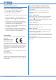
Connectivity
Inputs are via 3-pin 3.5 mm-pitch screw terminal connectors
on the rear panel (
5
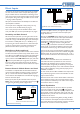
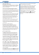
on g. 3). Connect microphones as
shown below. Note that if using an unbalanced microphone,
pins 1 and 2 should be connected together.
1
2
3
MIC INPUTS
Pin 1: Screen (Ground)
Pin 2: Cold/Antiphase (-)
Pin 3: Hot/Phase (+)
1
2
3
fig.6: Input wiring for microphones
BALANCED CONNECTIONUNBALANCED CONNECTION
Microphone Level Controls
A separate front panel level control (
8
and
9
on g. 2)
is provided for each mic input and these provide the user
with a convenient means of adjusting the audio level of the
microphones. The mic levels are unaffected by the operation
of the music level, music mute and remote music level
controls (if tted).
Gain Control
A preset mic gain control is provided adjacent to each
input connector (
6
on g. 3); this adjusts the mic pre-amp
gain in the range 10 dB to 50 dB. A high overload margin is
maintained at all gain settings, and a limiter circuit is always
active (see Microphone Limiter on this page). Nevertheless,
the gain controls should be set during installation so that
microphone distortion does not occur even when the front
panel MIC LEVEL controls are fully clockwise.
Microphone Equalisation
The microphone input stages each incorporate a xed
high pass lter. The lter attenuates signals below 100 Hz,
which helps to reduce the effects of microphone handling
noise. The mic inputs are then summed together and mixed
with the music channel (priority settings permitting) via an
adjustable EQ section.
The two pre-set EQ controls (
7
on g. 3) are on the
rear panel adjacent to the music EQ controls; the LF and
HF controls provide ±10 dB of adjustment below 100 Hz
and above 5 kHz respectively. After installation, some test
announcements should be made, ideally by the people who
will normally make them. The Mic EQ should be adjusted if
necessary to maximise voice clarity.
Microphone Limiter
The microphone channel incorporates a limiter circuit to
prevent amplier and speaker overloading and also to help
maintain more constant speech volume when the system is
used by different announcers. The limiter is set to restrict
the mic signals to a nominal 0 dBu, and if the mic gain and
level are set correctly, should be inaudible in operation on
normal speech. There are no internal or external controls.
Microphone Access Input
Access control for both microphone inputs is provided to
allow the CX261 to be interfaced to single-zone paging
mics such as the Cloud PM1. The access contacts work on
the short-to-ground system, which is compatible with the
majority of paging microphones.
The CX261 is shipped with the access control input disabled
for both microphone inputs. This allows immediate use with
standard microphones not tted with PTT (Press-to-Talk)
switches. If external access control is required, the internal
jumpers J6 (Mic 1) and J7 (Mic 2) must rst be removed. See
page 15 for location of the jumpers.
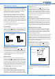
The access control input is a 3-pin 5 mm-pitch screw
terminal connector on the rear panel (
14
on g. 3). Mic
input 1 becomes active when M1 is connected to 0V; Mic
input 2 becomes active when M2 is connected to 0V.
0V M1 M2
Activate Mic input 1
A
ctivate Mic input 2
Part of external
paging mics
Access contacts
fig.7: Input wiring for microphones
See also the following section “Microphone Priority” for
further information on the use of the CX261 with paging
microphones.