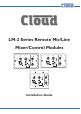
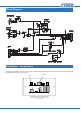
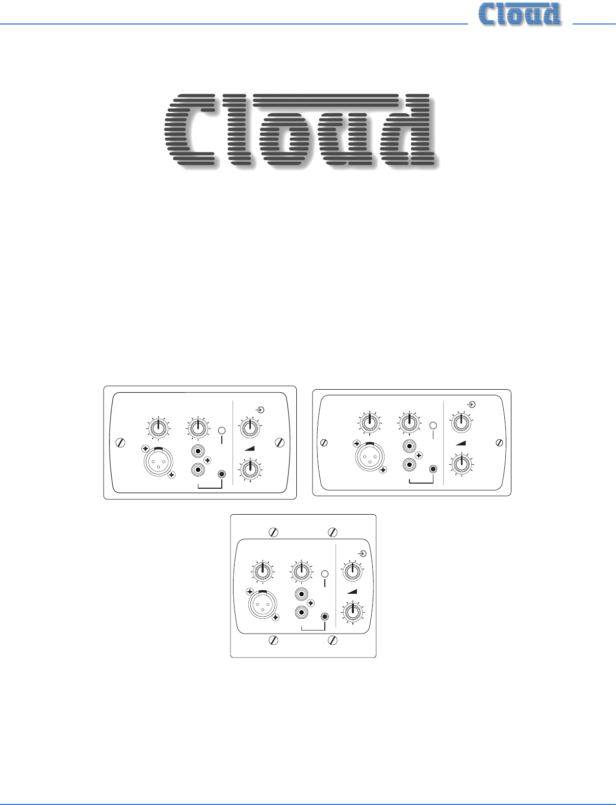
LM-2 Series Remote Mic/Line Mixer/Control Modules MIC LEVEL MIC LEVEL 5 6 MUSIC LEVEL 5 7 4 9 2 10 1 0 7 4 8 3 6 2 8 2 4 2 10 1 0 6 7 2 1 0 8 2 1 0 LINE INPUT MIC LEVEL 6 5 9 2 10 1 0 6 7 4 8 3 4 5 6 1 9 2 3 2 8 3 10 1 0 MIC PRIORITY 5 6 LINE INPUT 7 4 8 2 10 9 3 MIC INPUT 0 MUSIC LEVEL 7 4 10 1 LM-2D LM-2 5 9 2 MIC INPUT 10 7 8 3 9 3 6 4 7 4 LINE INPUT 6 5 6 5 10 MIC PRIORITY 5 4 1 9 3 3 2 8 0 MIC PRIORITY MIC
Contents Introduction..................................................................................................................................... 3 Mounting - mechanical................................................................................................................... 3 Faceplate Controls and Connections............................................................................................ 4 Block Diagram..........................................................................
Introduction The LM-2 is a remote module for use with the following Cloud products: • • Z4MK3 and Z8MK3 Zone Mixers 46-120 and 46-120MEDIA Zone Mixing Amplifiers It cannot be used with any other Cloud product. NOTE: Unless specifically stated otherwise, all references to “LM-2” in this Installation Guide can be taken to apply to all LM-2 mechanical and cosmetic variants.
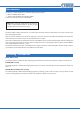
Faceplate Controls and Connections 4 5 MIC LEVEL 5 6 5 9 2 7 4 5 6 1 9 2 10 1 0 3 2 8 3 10 1 6 4 8 3 7 MUSIC LEVEL 7 4 6 0 MIC PRIORITY 5 6 7 4 8 9 3 2 MIC INPUT 1 LINE INPUT 2 10 1 3 0 8 LM-2 UK version illustrated 1. MIC INPUT – 3-pin XLR3F connector for dynamic microphones. Note that the LM-2 does not provide phantom power. 2.
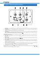
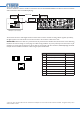
Block Diagram RJ45 RJ45 Installation - connections The LM-2 has two PCBs mounted on the rear of the faceplate.The OUTPUT RJ45 connector is located on the upper PCB while the LINK RJ45 connector is on the lower: LINK OUTPUT LOCATION OF REAR RJ45 CONNECTORS (‘DIN’ version illustrated. Sketch simplified; only primary components shown) LM-2 Installation Guide v1.
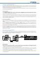
The LM-2’s OUTPUT connector should be connected to the host unit’s FACILITY PORT for the Zone in which it is installed* with screened Cat 5 cable and shielded RJ45 plugs. 100 m max Connect to OUTPUT socket Connect to FACILITY PORT Screened Cat 5 cable OUTPUT LINK LM-2 (UK version illustrated) The maximum total Cat 5 cable length should not exceed 100 m.
Configuring the Facility Port The mic and line inputs on the LM-2 module will be available in the Zone as soon as the module is connected to the host unit’s Facility Port for that Zone. The volume of the mic and line inputs will be determined solely by the level controls on the LM-2 faceplate and unaffected by any of the host unit’s front panel controls.
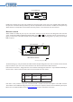
LM-2 LOWER PCB PHONOS XLR DISABLE LINK GATE LINK THESE TWO PADS NOTE: Users should be aware when using simultaneous microphone and/or music sources from multiple linked modules that the operation of the LM-2’s Priority function may become unpredictable, and if the function is enabled, one microphone may disable another, for example. We recommend that the Priority function is not used under these circumstances.
LM-2 Priority Operation If the MIC PRIORITY button on the LM-2 faceplate is not pressed, mic and/or line signals connected at the module will be routed to the Zone to whose Facility Port the LM-2 is wired, and heard through the audio system at volumes which can be controlled from the MIC LEVEL and MUSIC LEVEL controls on the faceplate. These locally-connected signals will be mixed within the host unit with any background music currently selected for that zone.
Power considerations The LM-2 is powered from the host unit’s FACILITY PORT via the Cat 5 connection. The LM-2 consumes 12 mA of current from the host unit’s power supply. In the majority of installations, the host unit will have ample spare current capacity to power one or more LM-2s. However, installers should note that this may not be case in a very large system with multiple remote modules in several Zones.
LM-2 Installation Guide v1.
Cloud Electronics Limited 140 Staniforth Road Sheffield S9 3HF England Tel: +44 (0)114 244 7051 Fax: +44 (0)114 242 5462 email: info@cloud.co.uk web: www.cloud.co.uk Cloud Electronics USA 2065 Sidewinder Drive, Suite 200, Park City, Utah 84060. United States of America. Toll Free: 0855 810 0161 Web: www.cloudusa.pro E-mail: sales@cloudusa.