VTX SERIES POWER AMPLIFIERS VTX 4120,VTX 4240,VTX 4400 CHANNEL 1 2 3 4 PROTECT O PEAK SIGNAL I POWER VTX 4120 4x 120W Amplifier CHANNEL 1 2 3 4 PROTECT O PEAK SIGNAL I POWER VTX 4240 4x 240W Amplifier CHANNEL 1 2 3 4 PROTECT O PEAK SIGNAL I POWER VTX 4400 4x 400W Amplifier Installation and User Guide
WARNING: To reduce the risk of fire or electric shock, do not expose this appliance to rain of moisture. CAUTION: Use of controls or adjustments or performance of prodedures other than those specified may result in hazardous radiation exposure.
Contents Safety Information......................................... 4 Safety Notes regarding Installation......................... 4 Safety Considerations and Information................. 4 General Description....................................... 5 VTX range main features.......................................... 5 Applicable Models....................................................... 5 Block Diagram................................................ 5 Front Panel Description..............................
Safety Information Caution - High Voltages Safety Notes regarding Installation Do not touch any part or terminal carrying the hazardous live symbol ( ) while power is supplied to the unit. •• Do not expose the unit to water or moisture. •• Do not expose the unit to naked flames. •• Do not block or restrict any air vent. •• Do not operate the unit in ambient temperatures above 35 C. O •• Do not touch any part or terminal carrying the hazardous live symbol ( the unit.
General Description Cloud VTX amplifiers are a range of high power multichannel audio amplifiers intended for use with high quality PA and music systems in locations where unquestionable long-term reliability is the primary consideration. As well as theatres, leisure centres and other major venues, they are also ideal for airport terminals, railways stations and similar large public spaces.
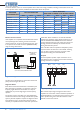
5 3 4 2 1 6 fig.
Installation Mechanical VTX amplifiers are designed to be mounted in a standard 19” equipment rack. The front panel is fitted with rackmount ears for this purpose. Each amplifier requires 2U of vertical rack space. See notes below regarding spacing and ventilation. Due to the units’ weight, the use of additional rear supports is strongly recommended. Connections and adjustments Inputs Each amplifier channel has an electronically-balanced input on a 3-pin, 3.5 mm-pitch screw terminal connector.
The three switches on the rear of VTX amplifiers allow a total of 8 routing possibilities, including 4-channel, dual stereo and mono operation with 4 channels paralleled.
100 V/70 V-line operation VTX amplifiers may be used to drive 100 V-line or 70 V-line speaker systems with the addition of appropriate external transformers. The Cloud CXL-100T is suitable for use with the Model VTX4120, and one transformer will be required per channel. A 2U rack-mounting tray (CXL-800) is also available to facilitate the installation of up to eight CXL-100Ts. Models VTX4240 and VTX4400 require transformers with a higher rating.
Bose® equalisation modules (optional) VTX amplifiers are compatible with Bose® Series II loudspeakers; a single-channel Bose® equalisation module may be fitted to as many channels as necessary.
Appendix Technical Specifications Output (Normal Mode) Output (Bridged Mode) Frequency Response High Pass Filter Distortion VTX4120 VTX4240 120 W (4Ω) 240 W (4Ω) 240 W (8Ω) 480 W (8Ω) 20 kHz to 20 kHz, +0/-1 dB; (HPF bypassed) -3 dB @ 65 Hz, slope 18 dB/octave (switchable) THD + N <0.03% @ 1 kHz, 1 W output, 4 Ω load Crosstalk Sensitivity Input Impedance Noise (rms) < -90 dB @ 1 kHz, -70 dB @ 10 kHz 0.
Location of jumpers and other internal components NOTE: The following jumpers and connectors are relevant to the optional VTX-WM1 surveillance card: J109 - J409 J110 - J410 J107 - 407A J801B, J802B Full details are in the VTX-WM1 Installation and User Manual BOSE® EQ Card Sockets BOSE® EQ Card Bypass Jumpers fig.9: Jumper Locations 12 VTX Series User Manual v1.
Factory default jumper settings table Jumper/Connector J104 J204 J304 J404 J108 J208 J308 J408 J107A J207A J307A J407A J801B J802B J805B* J806B* J109 J209 J309 J409 J110 J210 J310 J410 Function Bose® EQ card sockets Bose® EQ card bypass jumpers VTX-WM1 surveillance card interface sockets VTX-WM-1 card bypass jumpers Channel No. 1 2 3 4 1 2 3 4 1 2 3 4 All All 1&2 3&4 1 2 3 4 1 2 3 4 Default Setting Empty Present Empty Present *These connectors are on the lower (main) pcb.
Bose® is a registered trademark of The Bose Corporation. In the interest of continuing improvements Cloud Electronics Limited reserves the right to alter specifications without prior notice. 14 VTX Series User Manual v1.
Cloud Electronics Limited 140 Staniforth Road Sheffield S9 3HF England Tel: +44 (0)114 244 7051 Fax: +44 (0)114 242 5462 email: info@cloud.co.uk web: www.cloud.co.