VTX-WM1 Web Monitor Card Installation and User Manual
VTX-WM1 Installation Guide v1.
Contents Introduction....................................................................4 Applicability................................................................................................ 4 What’s in the box..................................................................................... 4 Installation......................................................................5 Preamble.....................................................................................................
Introduction Applicability Thank you for purchasing this Cloud product. The VTX-WM1 card may be fitted to the following amplifier models: The VTX-WM1 Web Monitor Card is an option for Cloud VTX Series power amplifiers.
Installation Remove these jumpers Preamble: The process of installing web monitor cards into VTX amplifiers is straightforward. If cards are being fitted to multiple amplifiers installed in one or more equipment racks, each rack will need to be provided with internal CAT5 wiring and an Ethernet switch. The Installation section of the manual describes in turn: i) fitting and testing cards in the amplifiers; ii) networking principles and iii) overall system configuration.
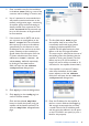
VTX-WM1 card’s Ethernet port to the network port on a computer using a standard CAT5 (or CAT5-e) network cable, terminated with RJ45 plugs. Either a “straight” or a “crossed” cable may be used, as the VTX-WM1 auto-detects the data lines. Power the amplifier on; it is not necessary at this stage to connect any audio inputs or outputs. Turn the computer on and check that it has a static IP address of the form 192.168.0.xxx, where xxx can be any value between 1 and 254 except 127.
Networking principles The VTX-WM1 card communicates with a computer – or the building’s IT system - using standard IP protocols over Ethernet. Physically, connections are made using CAT-5 cabling (4-pair UTP) terminated with RJ-45 connectors. If only one amplifier is to be used, it may be connected directly to a computer (as in Step 11 of the Installation Procedure), or connected to the IT infrastructure once it has been assigned a compatible IP address.
IP addresses and address allocation Every amplifier to be connected to the computer network must be given a unique IP (Internet Protocol) address. If the amplifiers are to be connected to a building’s IT infrastructure, the installer MUST check with the IT administrator to determine which addresses are available for use BEFORE configuring the amplifiers’ VTX-WM1 cards. 1. Disconnect all the amplifiers except one from the Ethernet switch. Also disconnect the switch from the building’s IT network.
5. Enter a suitable name for the installation in the Site Name field (e.g., name of the customer and/or building or location, etc.) 6. Use of a password is recommended as it will prevent unauthorised access to the network configuration pages - monitoring of amplifier performance and settings is always possible. Enter a password in the Site Password field. A password may be up to 64 characters in length and will be case sensitive. 7.
13. The VTX-WM1 card has an on-board clock/calendar, which needs to be set for the Event Log to be meaningful. The default Current Time will be midnight on Jan. 1st. 2000; click the adjacent Set button to open the Clock setting window. Enter the current date and time in the five fields in the format yyyy-mm-dd hh:mm and click Apply. 14. Click Apply on the Amplifier Properties page to confirm the data entered. 15.
Model type is confirmed, and any Network faults.
unit’s network status, server status and IP address. Only one amplifier in the list should have a green tick in the Server column. Note that this page automatically refreshes every few seconds, as the network is continuously polled. Clicking the Test button in the Test connection column causes the amplifier in question to be polled immediately (often referred to as “pinging”); it will then report its current status. As with the Home page, clicking on a Unit Name will open the Amplifier Status page.
impedance at the frequency to be used. The upper pane of the Test List page is concerned with this initialisation. Impedance Tests The VTX-WM1 card includes a variable frequency test oscillator which may be programmed to apply a test tone (at 40 dB below the amplifier’s maximum output level) to the amplifier output at a future date and time, and, if desired, at regular intervals thereafter. (It is recommended that tests are scheduled for the hours of building non-occupation).
Scheduling the tests The test scheduler lets you set the date and time at which the next impedance test will be executed, and whether it is to be repeated at regular intervals thereafter. It also lets you set the schedule independently for each amplifier channel, together with the frequency to be used and the tolerance to be applied.
Appendix Location of PCB jumpers and connectors POWER CONNECTOR Factory default jumper settings table JUMPER J810 J811 J812 J813 J817 PURPOSE FUNCTION DEFAULT Reserved Force defaults Restores all factory default settings* Off J816 Force config Disables password protection Off J815 J814 Force IP
Specifications Tone Generator Test Signal Level 40 dB below max amp output Injected post level controls, other channels muted.