
User guide


VTX Series User Manual v1.0 7
Installation
Mechanical
VTX ampliers are designed to be mounted in a standard
19” equipment rack. The front panel is tted with rackmount
ears for this purpose. Each amplier requires 2U of
vertical rack space. See notes below regarding spacing and
ventilation.
Due to the units’ weight, the use of additional rear supports
is strongly recommended.
Ventilation
VTX ampliers are force cooled by two thermostatically-
controlled fans mounted internally on the main PCB. The
fans are always operational, and run at a higher speed when
required.
Always allow adequate space around the amplier(s) to
allow a free ow of air through the unit(s). Ensure that cable
bundles or other items do not obstruct any grilles.
In 19” rack applications we recommend leaving 1U of rack
space above and below each unit. Plain 1U blank panels,
not slotted ventilation panels should be used, as the latter
reduce the effect of forced-air cooling. The direction of
airow in VTX ampliers is front-to-rear; it is recommended
not to mix these ampliers with other equipment employing
forced-air cooling which acts in the opposite direction
within the same rack.
If using the amplier free standing, we recommend tting the
feet supplied and placing the unit on a at surface, leaving the
ventilation grilles free from any obstructions.
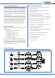
Connections and adjustments
Inputs
Each amplier channel has an electronically-balanced input on
a 3-pin, 3.5 mm-pitch screw terminal connector. The mating
connector is supplied. Twin-core screened cable should be
used when driving the amplier inputs from a device with a
balanced output. Single-core screened cable can be used when
connecting to an unbalanced source. Wire the inputs to the
source devices using the convention shown below:
Sensitivity and Gain Control
Control of input level is provided by a preset rotary
control adjacent to each input connector. The control
should be adjusted using a trimtool or small screwdriver.
Full attenuation of the input signal – i.e., zero output – is
obtained with the control fully anti-clockwise. Maximum
sensitivity is with the control fully clockwise; at this setting
the maximum output level will be produced for an input
signal level of 0.775 Vrms (0 dBu).
We recommend that the level for each channel should be
adjusted after installation is complete to ensure adequate,
but not excessive sound levels are achieved with the
programme material that will be used in practice.
Input Routing
To facilitate the use of the ampliers in a variety of different
multi-channel applications, input selection switches are
provided on all channels except Ch1. This gives the installer
an easy method of paralleling channels from a single input.
Refer also to g.1 on page 5.
The options are summarised in the table below:
SOURCE FOR Chs. 2-4
Button position: OUT IN
Channel 2 In 1 In 2
Channel 3 In 1 In 3
Channel 4 In 2* In 4
*post Ch 2 switch
g.4: Input Wiring