
User guide


VTX Series User Manual v1.08
The three switches on the rear of VTX ampliers allow a total of 8 routing possibilities, including 4-channel, dual stereo and
mono operation with 4 channels paralleled. The table below claries the options:
AMPLIFIER
CONFIGURATION
BUTTON POSITION
INPUT ROUTING:
AMPLIFIER CHANNELS FED BY EACH INPUT
CH 2 CH 3 CH 4 IN 1 IN 2 IN 3 IN 4
4-channel IN IN IN CH 1 CH 2 CH 3 CH 4
Dual mono + stereo OUT IN IN CHS 1 & 2 CH 3 CH 4
Dual mono + stereo IN OUT IN CHS 1 & 3 CH 2 CH 4
Treble mono + 1 OUT OUT IN CHS 1, 2 & 3 CH 4
Dual mono + stereo IN IN OUT CH 1 CHS 2 & 4 CH 3
Treble mono + 1 OUT IN OUT CHS 1, 2 & 4 CH 3
Dual stereo IN OUT OUT CHS 1 & 3 CHS 2 & 4
Quad mono OUT OUT OUT CHS 1, 2, 3 & 4
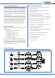
Remote Control of Level
VTX ampliers are compatible with standard Cloud remote
control plates Type RL-1, allowing control of level from a
remote position. RL-1s may be connected at the rear 3-pin,
5 mm-pitch screw terminal connectors (REMOTE LEVEL),
using the wiring shown below.
Use two-core screened cable to connect the remote level
plate (maximum length 100 metres).
High Pass Filters
Each channel of the VTX is tted with a switchable hi-pass
lter, which may be switched in as required to reject low-
frequency signals below 65 Hz. The lter has a slope of
18 dB/octave, to provide a high degree of low frequency
rejection.
The primary purpose of the lter is to avoid loudspeaker
transformer saturation when driving 100 V/70 V-line speaker
systems. (The VTX ampliers’ outputs are designed to drive
low-impedances only, so an external transformer will be
necessary for amplier channels to drive such systems. The
Cloud CXL-100T is suitable for use with the VTX4120;
transformers with higher ratings will be necessary for use
with the VTX4240 and VTX4400). Transformer saturation
creates unpleasant distortion and stresses the system, and
the high pass lter should always be switched in when
driving 100 V/70 V-line systems.
Use of the lter with low-impedance loudspeaker systems
is optional and at the discretion of the installer; switching
it in may help to enhance the clarity of speech, reduce
microphone handling noise and breath blasts.
Outputs
The VTX ampliers’ speaker output connections are on
two adjacent 4-pin, 5 mm-pitch screw-terminal connectors
(mating connectors are supplied).
CH 1CH 2CH 1
CH 3CH 4
-+-+-+-+
Each channel’s output stage is designed to drive into an
impedance of not less than 4 ohms. Check the impedance of
the loudspeaker(s) in use and, taking into account any series
and/or parallel wiring, ensure that the total load on each
channel is not less than 4 ohms.
g.6: Output Wiring
g.5: RL-1 Wiring
1
2
3
REMOTE MUSIC
CONTROL
CONNECTOR
1
2
3
RL-1
USE TWO-CORE SCREENED CABLE