Z4II & Z8II ZONE MIXERS Installation and User Guide
Contents Safety Information................................... 4 Setting Up & Operation........................ 16 Safety Notes Regarding Installation.................... 4 Music Inputs......................................................... 16 Gain & level........................................................................ 16 Local/remote control....................................................... 16 Conformities..........................................................
Safety Information Safety Notes Regarding Installation •• Do not expose the unit to water or moisture. •• Do not expose the unit to naked flames. •• Do not block or restrict any air vent. •• Do not operate the unit in ambient temperatures above 35 °C. •• Do not touch any part or terminal carrying the hazardous live symbol ( the unit.
Overview Introduction What’s in the box Thank you for purchasing this Cloud Zone Mixer. We are confident that you will be pleased with its performance, features, flexibility and reliability. Unpack the Z8II or Z4II and its accessories with care. It is always a good idea to store all packaging (if practical), in case you ever need to return the unit to your Cloud dealer for any reason. The Cloud Z4II and Z8II are versatile analogue multizone audio mixers.
Optional System Components The following components may form part of the audio system and may be ordered separately if required. They may also be retrofitted to a system at a later time. control of zone music level and source. The music ducking facility is also provided for the mic input. See page 12 (Connecting an LM-1 remote input plate) and page 18 (LM-1 and DM-1 active input plates) for more information.
PM Series Paging Microphones PM1 Paging Microphone fig.5: PM16 fig.6: PM1 Cloud PM paging microphones may be connected directly to the Z8II and Z4II. Models are available which can page to 4, 8, 12 or 16 zones. Clearly, not all zones on the ‘higher’ models can be addressed with only one zone mixer. See page 13 (Connecting a PM4/8/12/16 paging mic) for more information. The Cloud PM1 paging microphone is also compatible with the Z8II and Z4II. It is a much simpler unit which addresses only one zone.
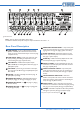
1 10 6 7 4 9 5 3 8 10 2 fig.8: Z8II Front Panel Note - The front panel of the Z8II is shown above. The Z4II’s is identical, except that it only has controls for zones 1 - 4. Front Panel Description 1 MUSIC SOURCE – 6-way rotary switch selecting which Line Input (1 to 6) will be the music source for each zone. See page 16 (Local/remote control) 2 MUSIC LEVEL – adjusts the music level in each zone.
10 11 3 4 13 12 5 6 7 14 8 16 1 2 9 15 fig.9: Z8II Rear Panel Note - The rear panel of the Z8II is shown above. The Z4II’s is identical, except that it only has output connections for zones 1 - 4. Rear Panel Description 1 2 LINE INPUTS – 6 pairs of RCA (phono) sockets (Line 1 to Line 6) for connection of music sources. Inputs are stereo, summed internally to mono.
Installation Hardware Considerations System Connections The Z4II and Z8II Zone Mixers are built in 3U-high 19” rack mount enclosures. It is recommended that the Zone Mixer is installed in a 19” rack wherever possible. The units are approx. 160 mm deep, but 250 mm of rack depth should be available to allow for rear connectors and cabling.
manuals with each item for guidance on how the outputs should be connected to an unbalanced input. However, the wiring methods shown in fig.11 and fig.12 will work in a large number of cases. If hum or other distortion is found to result, try disconnecting the ‘cold’ leg of the balanced output (pin 3 on XLRs).
Microphone inputs Connecting a DM-1 remote input plate Mic 1 and Mic 2 inputs are intended for the direct connection of microphones. They are electronically balanced and transformerless with an input impedance of greater than 2 kΩ and optimised for use with microphones of 200 to 600 Ω impedance. Unbalanced microphones may be used by connecting pins 3 to pin 1 (cable screen) in the XLR plug. 15 V phantom power is available, see page 16 (Phantom Power).
(either by a local PSU or via the CDPM digital network from another PM unit). Z4 II /Z8 II FACILITY PORT 1 6 2 7 3 PM8 PAGING MICROPHONE 8 4 TERM1 9 TERM2 TERM8 5 +V 0V Z1 Z2 Z3 Z4 Z5 Z6 Z7 Z8 Z1 Z2 Z3 Z4 Z5 Z6 Z7 Z8 HOT COLD GND CABLE SCREEN 10 9 8 7 6 5 4 3 2 1 LM-1 (uppermost) PCB fig.17: LM-1 Facility port Note that the cable’s screen should be connected to terminal 3 at the DM-1 end, and to the shell of the Dsub connector at the mixer end.
Connecting a PM1 paging mic Music Control The PM 1 is a simple, passive paging microphone suitable for situations where announcements are always made to the same zone(s). It can be connected directly to Z8II/Z4II zone mixers, the control cable being wired to the pin(s) of the Zone Access port corresponding to the zone(s) in which announcements are required. Any or all of the zones may be paralleled if multiple zones need to operate from the PM1.
Connecting an RSL-6 remote control plate Wire the remote control plate as shown below. Twin-andscreen cable should be used. Maximum reliable cable run is 100 m. MUSIC MUTE INPUT 1 REMOTE SOURCE & LEVEL CONTROL WIRING 2 3 REMOTE MUSIC CONTROL PORT RSL-6 1 2 RELAY 1 2 3 NORMALLY OPEN (NO) CONNECTION USE TWO-CORE SCREENED CABLE fig.21: Music mute, normally open MUSIC MUTE INPUT fig.
Setting Up & Operation Music Inputs Microphone Inputs Gain & level Phantom Power To avoid dramatic changes in volume when switching between sources, the Z8II/Z4II’s music inputs are provided with preset gain trim controls ( 2 on page 9 - Rear Panel Description). These vary the input sensitivity from -12 dBu (195 mV) to +8 dBu (2.0 V).
Gain & level The paging mic input has a rear panel preset gain control ( 7 on page 9). A wide range of gain is available and there should be no problem in obtaining a satisfactory level from most paging microphones. The mic gain control should be adjusted by making an announcement. Set the front panel Paging Mic Level preset control at about halfway and listen in a convenient zone; the rear panel gain control should be carefully advanced until the announcement is heard clearly and without distortion.
Options and Additional Information LM-1 and DM-1 active input plates – general considerations Cloud DM-1 and LM-1 remote input plates are the same physical size as a double-gang UK electrical socket and can be mounted in the recessed back box provided or in a standard surface-mounting box of 35 mm depth.
Using the Facility Ports as auxiliary zone inputs PIN The Facility Port provides a balanced audio input. If a port is not connected to DM-1 or LM-1 remote input plates, it may be used as a direct input to the zone from other equipment forming part of the system (for example, a permanently installed DJ mixer which only ever needs to feed its output to that particular zone.) USE 1 2 0V ref.
Music source Music source for a zone may be controlled by applying various DC voltages of between 0 and +10 V to pin 3, the 0 V reference being connected to pin 1. 0 V at pin 3 will select Line input 6 and between +7.5 and +9 V will select Line input 1. The other line inputs will be selected with intermediate voltages. Taking pin 3 above +9 V will deselect all inputs, making the zone effectively ‘off’ for music. The table below lists the DC voltages required at pin 3 to select each line input.
Z4II & Z8II Installation and User Manual v1.
Appendix Application example The DCM-1 will find application in many types of premises, including shops, bars, hotels, schools, conference centres, offices, etc. A typical example using most of the Zone Mixer’s facilities is given below.
PCB jumper location and settings The Z4II and Z8II have various internal jumpers, the setting of which may require alteration during installation. Note that there are jumpers on both the motherboard and the individual zone sub-cards. The table below lists each jumper and its purpose, together with the factory default setting. Note that options selectable by jumpers on the zone sub-board are per-zone, and will need to be set on as many zone sub-boards as necessary.
ZONE 1 ZONE 2 ZONE 3 ZONE 4 ZONE 5* ZONE 6* ZONE 7* ZONE 8* FRONT OF UNIT J2 J1 J3 ZONE SUB-CARDS J4 MOTHERBOARD (at bottom of chassis) * Z8 II ONLY POWER TRANSFORMER KEY: Jumper with two possible positions; black square indicates factory default setting. fig.27: Jumper locations J6 J3 J2 (COMPONENT SIDE) fig.28: Sub-card jumper locations 24 Z4II & Z8II Installation and User Manual v1.
PSU capability and optional device current consumption In addition to supplying the Zone Mixer’s circuitry, the internal PSU has the capacity to power some additional items which may form part of a complete system. These include LM-1 and DM-1 active remote input plates (via the Facility Port), Bose® EQ cards (fitted internally), and possibly a PM Series paging microphone (powered via the Access Port).
Technical Specifications Z4II & Z8II Line Inputs Frequency Response Distortion Sensitivity Input Gain Control Input Impedance Headroom Noise 20 Hz - 20 kHz, ±0.5 dB <0.05% 20 Hz - 20 kHz 195 mV (-12 dBu) to 2.0 V (+8 dBu) 20 dB range 47 kΩ >20 dB -90 dB A-weighted (0 dB gain) Microphone Inputs Frequency Response Distortion Gain Range Input Impedance Phantom power Headroom Noise Equalisation 100 Hz / -3 dB (filter) 20 kHz ±0.5 dB <0.
Notes Bose® is a registered trademark of The Bose Corporation. In the interest of continuing improvements Cloud Electronics Limited reserves the right to alter specifications without prior notice. Z4II & Z8II Installation and User Manual v1.
Cloud Electronics Limited 140 Staniforth Road Sheffield S9 3HF England Tel: +44 (0)114 244 7051 Fax: +44 (0)114 242 5462 email: info@cloud.co.uk web: www.cloud.co.