
User guide


10
Z4
II
& Z8
II
:
Installation and User Guide
22/10/04 V9
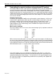
24 Plug-in Active
Equalisation modules.
Each zone board has the facility to connect a plug-in equalisation module. When fitting a
module to one of the zone boards, proceed as follows:
•
Disconnect the power connector from the mixer.
•
Remove the top panel.
•
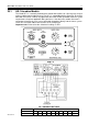
Locate the zone board for the zone to which the EQ card is to be fitted. The zone boards
run vertically up the inside of the unit.
•
Locate CON 2, the EQ card connector on the zone board. Fit the EQ module to the
connector. The EQ card should be perpendicular to the zone board.
•
Apply moderate pressure to the EQ module, towards the zone board, until it locates with a
click.
•
Replace the top panel
Zone board fitted with EQ Module
Important note:
Refer to Section 19 before installing an Active Equalisation Module
EQ Modules currently available are:
Bose® M8, M32, MA12, 402, 502A, 802, MB4, MB24, 502B, 502BEX, LT3302, LT4402,
LT9402, LT9702, M16.
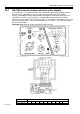
25 Active Modules – general specification.
The Cloud AE-1, DM-1 & LM-1 are the same physical size as a double UK electrical socket
(13A type) and can be mounted in the recessed back box provided or be surfaced mounted
in a standard 35mm deep housing. The modules should be connected to the facility input of
the host mixer using a single multi-core screened cable. The module terminations are
conventional screw terminals and the facility input on the host mixer is a 9-pin sub-D type
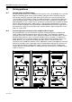
connector. A suitable 9 pin sub-D connector is provided. G
REAT CARE MUST BE TAKEN WHEN
TERMINATING THE MODULES
;
POWER IS DERIVED FROM THE HOST MIXER AND CERTAIN WIRING
ERRORS CAN CAUSE POWER SUPPLY PROBLEMS RESULTING IN TEMPORARY FAILURE OF THE
MIXER
;
ALWAYS CHECK YOUR WIRING BEFORE TESTING THE SYSTEM
.
Please refer to section 18 for further details of the facility input connector.