Instruction Manual Stand-Alone 4 Channel Digital Video Recorder Model CDR0430, CDR0410 Copyright ©2009 Clover Electronics U.S.A. All Rights Reserved.
Contents Contents 1. Unpacking 6 About This Unit 7 2. Features 8 3. Specifications 9 4. Installation 4-1. 4-2. 4-3. 4-4. 10 What to do before Installation Installation Check List Controls and Connectors on the DVR System Connection 10 11 12 15 4-4-1. Camera Connection 4-4-2. Video Output Connection / VGA Connection 4-4-3. Audio Connection 16 16 16 4-4-4. 4-4-5. 4-4-6. 4-4-7. 17 17 17 17 Network Cable Connection Mouse Connection Sensor Connection Alarm Output Connection 4-5.
Contents 5-5-4. PAN / TILT & ZOOM 28 5-5-4-1. How to Connect PAN / TILT Device 28 5-5-4-2. How to use PAN / TILT 29 5-5-4-3. How to use ZOOM / FOCUS 29 5-5-5. Toggle OSD ON/ OFF 5-6. Recording 30 31 5-6-1. Manual Recording 5-6-2. Automatic Recording 31 31 5-7. Playback 32 5-7-1. Set Playback Time 32 5-7-2. Search by Event 5-7-3. How to Search through Playback 35 36 5-8. Copying to USB 37 6. Setup 40 6-1. Setup Menu 6-2. Camera Setup 40 41 6-2-1. Channel 42 6-2-2. Display 6-2-3.
Contents 6-6. Screen Setup 64 6-6-1. Border Setup 65 6-6-2. Video Adjustment 6-6-3. Sequence Setup 65 65 6-7. Audio Setup 66 6-7-1. Audio Record Setup 66 6-7-2. Mute Setup 6-7-3. Input / Output Volume Setup 67 67 6-8. System Setup 68 6-8-1. Hard Disk Setup 68 6-8-1-1. Overwrite Option 69 6-8-1-2. Format HDD 69 6-8-1-3. Hard Disk Drive Information 71 6-8-2. Password Change 72 6-8-3. Time Set 76 6-8-3-1. Time Zone Setup 76 6-8-3-2. Time Setup 77 6-8-3-3.
Contents 6-11. Exit 89 7. Viewer 90 7-1. Installing / Running the Viewer 7-2. Player 91 92 7-2-1. Menu 93 7-2-2. 7-2-3. 7-2-4. 7-2-5. 94 95 96 98 Icons How to Open a Video File How to Save as AVI file How to Capture a Screen 7-3. Network Viewer 99 7-3-1. How to Connect to the DVR 7-3-2. Menu 7-3-3.
Contents About this manual This is the instruction manual for the Stand-Alone type DVR, CDR0430 and CDR0410. This manual describes how to install and operate the DVR and provides information regarding specifications and features of this product. Please be sure to read this manual and follow the instructions when installing the Digital Video Recorder. If you have any questions or problems installing, please contact Clover Electronics at 877-327-5000.
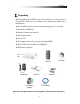
Contents 1. Unpacking When unpacking the DVR Unit, please be cautious not to drop, throw or hit with force. This may cause damage to the product that could lead to malfunctions. Before Installation please check if the following objects are included.
Contents About This Unit You have just purchased a state-of-the-art 4 CH Stand Alone DVR with network connection. The most interesting feature of this system is the USB Firmware updating option, which enables software upgrading and software management to be done at home with a computer and a USB drive, instead of sending the DVR. To enhance the user friendliness of this DVR system, the user can operate with both the remote controller and a PS2 mouse (option).
Contents 2.
Contents 3.
Contents 4. Installation 4-1. What to do before Installation Make sure all the required hardware is available.
Contents 4-2.
Contents 4-3.
Contents ÚC Back to Quad Screen Mode & Auto Screen - Auto Screen B Display each channel in full screen followed by Quad screen for the duration set by the user.
Contents Rear Audio connection port PS/2 Mouse port VGA Port Camera Input port Video output device port A DC 12V adaptor port Network connection port ÚA Alarm Input Alarm output Grounding RS485 Alarm Input : The user can connect to ports 1 ~ 4. Grounding : All alarm input must be connected to this grounding port. Alarm Output : Connect one line to “COM” and the other to either Normal Open(N.O) or Normal Close(N.
Contents 4-4.
Contents 4-4-1. Camera Connection Connect the cameras to the Video Input (BNC Connector) on the back of the unit as shown. On this unit, the user can connect up to 4 Cameras. 4-4-2. Video Output Connection / VGA Connection Connect the composite monitor to any one of the BNC ports. This unit can support up to two composite monitors at the same time. The video output to the two monitors will be the same. Connect the VGA Monitor’s connector to the “DSUB 15 Pin Connector” on the rear of the unit.
Contents 4-4-4. Network Cable Connection (Not Available on CDR0410) Our Network Cable Connector is designed for RJ45 type cables. Connect the Network cable here to utilize the network function of the DVR 4-4-5. Mouse Connection This port is designed for PS/2 devices. Connect the mouse here to utilize the device in the DVR system 4-4-6. Sensor Connection The DVR unit has 4 Input ports for Sensors. . trigger To connect, press the trigger to open the socket Ú Note : the trigger may be difficult to press.
Contents 4-5. Step By Step Installation Set Cameras in position Set Audio Input device in position Set Sensor device in position Set DVR unit in position. Ú Note : The DVR unit must use the 12V adaptor that comes with the set. Usage of other adaptors may cause malfunction. Connect DVR unit with the Cameras, Audio Input device and Sensors. Connect a VGA monitor or (and) a composite monitor to the DVR unit. Check if the Video Output and Audio Output are clear.
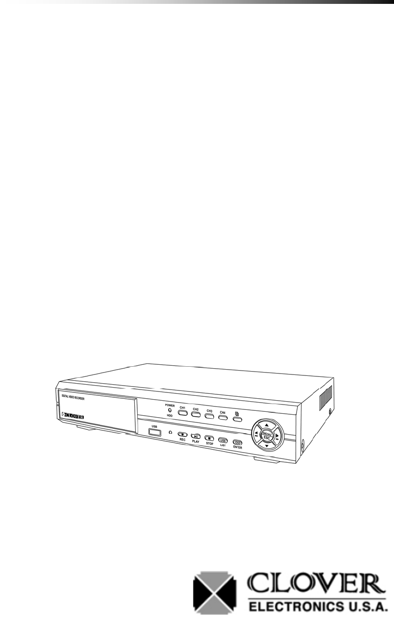
Contents 5. How to Operate 5-1. General Operation You can operate the functions of the system by using the buttons located at the front panel of the DVR unit, as well as the remote controller and a PS/2 mouse. The system status is indicated by either the LED lights located near the center of the front panel, or the monitor. This system is protected from pressing the buttons by accident, but be careful when using the “Hard Disk Setup” option, for this may lead to data loss, and the “Password Change” option.
Contents 5-2.
Contents 9 Screen : 9 Split Screen mode (Not supported in 4 CH DVR) Quad Screen : Quad Split Screen mode Number keys : Used to select camera in Full Screen mode Play : Used to select Playback mode Enter : Used to select a certain menu / option OSD : Used to select OSD (On Screen Display) ON / OFF PAN/TILT : Used to select PAN/TILT option from Camera direction to Camera Zoom & Focus Auto Sequencing : Used to select Auto Screen Mode.
Contents 5-3. PS/2 Mouse (Option) Wheel Right button Left button PS/2 Connection Left Button : Double click to select screen, single click to toggle. Right Button : click for menu, or to use as exit button. Wheel : Not used PS/2 : This DVR system does not support USB mouse. If necessary, Please use the PS/2 type mouse (not included).
Contents 5-4. Running for the First Time When you turn on the power for the very first time, the screen will be shown as above. You must press the Enter button on the Remote controller or the Front Panel to proceed. If you press the Enter Button, “Disk0 : PRESS [ENTER] FORMAT, [STOP] CANCEL” message will show.
Contents Press the Enter Button again to format the HDD and make it ready for use If HDD Format is successful the first screen that comes out will be as shown above Ú If there is an error with the camera or if there is no camera connected to the port, a blue screen will appear as shown below.
Contents 5-5. Display Screens Motion Detect Icon Camera Number Camera Number Recording Icon Lock Icon Network HDD Use Date/Time Alarm Trigger Schedule Recording Sensor Motion Detect 5-5-1. Quad Split Screen Display The Quad Split Screen Display is the default display of this DVR unit.
Contents 5-5-2. Full Screen Display Motion Detect Icon Camera Number Recording Icon PAN/TILT Icon HDD Use Alarm Trigger Network Sensor Date/Time Record Schedule Motion Detect During Full Screen Display mode the user can see the video from a certain camera in a larger scale. To view in Full Screen Display mode, press the Camera number button on the Front panel, or on the remote controller. You can also select a screen by double clicking your mouse.
Contents You can navigate through these options by using the Enter key. While utilizing the PAN / TILT option, use the direction keys on the Front Panel, or the remote controller. In ZOOM mode, the up and down keys (T, S) are used as zoom in and zoom out, the left and right keys(X, W) are used to adjust the focus of the camera. Ú For more information about PAN / TILT and ZOOM, please refer to the manual supplied with your camera. 5-5-3.
Contents Auto Sequence The time frame of the screen shown can be adjusted through the SCREEN option in the Menu. (Refer to Chapter 6-6-3. Sequence Setup) 5-5-4. PAN / TILT & ZOOM In this chapter, the user will be instructed on how to connect a PAN / TILT Camera and how to operate it through the DVR Unit. Ú Refer to Camera Specs / Manual for information 5-5-4-1.
Contents 5-5-4-2. How to use PAN / TILT The PAN / TILT function can be used in Full Screen Mode only. When in Full Screen mode, press the button to enter PAN / TILT mode. When PAN / TILT Mode is initialized, the icon will show on the bottom of the screen. When shows on the screen, the Direction Keys on the Remote Controller and the Front Panel will work to move the camera. 5-5-4-3.
Contents 5-5-5. OSD ON / OFF By using the OSD button on either the Front Panel, or the Remote Controller, one can toggle the OSD (On Screen Display) ON and OFF. The user can select OSD ON & OFF during Full Screen Display mode and Quad Split Screen mode. Ú If there is a shift in Screen modes, the OSD will appear again.
Contents 5-6. Recording 5-6-1. Manual Recording Front Panel The user can manually start recording the video footage by pressing the buttons shown. Remote The Manual Recording will start recording only if the Sensor, Motion Detect and Record Schedule is not set. The icons are shown below. Sensor / Motion / Schedule 5-6-2.
Contents 5-7. Playback 5-7-1. Set Playback Time The screen as shown above will appear if the Play button on either the Front Panel or the Remote controller is pressed. To adjust the starting point of the playback, press the Enter key on either the Front Panel or the Remote Controller or place your mouse pointer on the numbers.
Contents When the enter key is pressed or the mouse is clicked on the numbers, red arrows will appear on the screen as shown below. The starting time can be adjusted using the Up / Down keys to change the value, Left / Right keys to change the digit or by clicking on the arrows.
Contents After setting the starting point, to Start Playback, exit the editing mode by pressing the Menu/Stop/ESC Button and then select the Search option and press the enter key or just click on Search with your mouse.
Contents 5-7-2. Search by Event The screen will show as above if the List button is pressed in the Live mode. From the list as above, the user can search, using the Direction keys, for the event the user wishes to watch the playback from. Ú The Up / Down keys (S, T) are used to scroll through the list and the Left / Right keys (W, X) are used to go through the pages or you can use your mouse to choose your event.
Contents 5-7-3. How to Search Through Playback During Playback Mode, the buttons on both the Front Panel and the Remote Controller work differently from how it did during Live Mode. The functions of the buttons during Playback mode are as shown.
Contents 5-8. Copying to USB This option enables the user to extract certain amount of video data from the DVR Unit to a USB Memory. By Utilizing a USB Memory instead of a CD / DVD allows the user to extract and transport the video data more efficiently. The steps to copy the video data to a USB memory is as shown. Step 1 : Format your USB Memory.
Contents Press the Menu button to exit editing the time and date, Down button to select Search and press Enter to proceed.
Contents Step 5 : When the USB button is pressed after setting the time range The process of reading the USB memory takes time. Please be patient. When the Enter button is pressed, the DVR will write the data to the memory. During this stage, the status will be shown by the increase of “Writing to USB” file size, and the decrease of the “Time to Remain” Ú Please note that this procedure may take time depending on the size and speed of reading the USB memory.
Contents 6. Setup 6-1. Setup Menu The Setup Menu can be toggled by pressing the Menu Button from the Front Panel or the Remote Controller. The Menu provides options to the user to customize the DVR unit on how it operates. The menu is designed to be safe from unwanted operations executed by pressing the wrong buttons by mistake. But be aware that the Hard Disk Setup menu can lead to unwanted memory loss. Ú If you ever lose your password, please contact Clover Electronics.
Contents 6-2. Camera Setup When the Menu Screen is toggled, the Camera is selected by default. Press the Enter button on either the Front Panel or the Remote Controller to enter the Camera option. Clicking on the option with your mouse can also be used.
Contents 6-2-1. Channel To enter the Camera Setup mode, select the Camera Setup option from the Main Menu and press Enter, or click on the option using your mouse. The Channel option is used to navigate through each camera in order to adjust the Camera Display option. The Channel can be changed using the Left / Right keys (W, X) or by clicking on the red arrows.
Contents 6-2-2. Display Press the Menu button to show the main menu From the main menu, select the Camera option and press Enter. To search through the menu, use the Up / Down buttons. From the Camera option, select the camera of which the options should apply to by using the Left / Right buttons while selecting the Channel option. From the Camera option, use the Up / Down arrows to select the Display option and use the Left / Right arrows to choose ON / OFF.
Contents From the main menu, press the Menu button to exit. Select the Exit & Save Changes option to exit and save changes. If the Display option was set to OFF the screen for the corresponding camera will turn black. Ú Even if the cameras are not connected (shown blue as above) will turn black if turned Off.
Contents 6-2-3. Camera Color Option The user can adjust the Camera Display just like adjusting any other video output such as monitors or TV’s. Use the Left / Right keys (W, X) to adjust the value, and Up / Down keys (S, T) to navigate through the options.
Contents 6-3. Record Setup The Record menu is for the user to customize the quality of the picture recorded, how long it is recorded and when it is recorded for automatic recording.
Contents 6-3-1. Record Speed To enter the Record Setup, Select the Record Setup option from the Main menu. The Record Speed option is to adjust how many fields each video footage should record per second. The more the fields, better the quality of the video stream.
Contents Ú Please note that the total Fields that could be used is 60. Allocate the fields used by each camera according to priority. The values can be changed using the Left / Right keys(W, X) on the Front Panel or the Remote Controller and by clicking on the red arrows with the PS/2 Mouse. Ú Please note that is a camera was turned OFF in the Camera Display option (refer to chapter 6-2-2. Display) the field for that certain camera will be set to 0.
Contents 6-3-2. Record Quality There are 3 options for Record Qualities (High, Normal and Low). Select the Recording Quality using the Left / Right buttons.
Contents 6-3-3. Hold Time The Hold Time option is used to set the time to record when an event is triggered by the sensors set by the user, or by Motion Detection. (For information on Motion Detection refer to Chapter 6-5 Motion Detection) To change the value, use the Left / Right buttons while selecting the Hold time option.
Contents 6-3-4. Schedule Recording For Schedule Recording setup, first enter the Record Setup option from the main menu by pressing the menu button Ö select the Record option using the Up / Down button and press enter. From the Record Setup option, select the Schedule Recording option using the Up / Down button and press enter. From the Record Schedule option, one can select the time frame of when the DVR should record. Each cell represents 1H.
Contents Exit & Save Changes to apply the Schedule Recording. If the schedule is applied, a clock icon ( ) will appear at the bottom of the screen as shown. If the Record button is pressed while this Icon is present, the video will only be recorded during that time frame set by the user. Ú The Play key is used to toggle all sectors. This will affect all the sectors at the same time, and set the sectors to the same option.
Contents 6-4. Sensor The Sensor option of the menu is used to customize the alarm function of the DVR unit. Press Enter while selecting this option or click on the Sensor option to adjust.
Contents 6-4-1. Relay Output To enter the Sensor Setup mode, select the Sensor Setup option from the Main menu and press Enter. The Relay Output option, like the Hold Time option in the Record Menu, is used to set how long the alarm should be relayed for when the sensor is triggered. Ú The Sensors must be connected correctly to the terminal block at the rear panel of the DVR unit for the alarm to work. Be sure to connect all sensors to the Ground port as well as the Sensor Input ports.
Contents 6-4-2. Sensor Setup The Sensor (PIR: Passive Infrared) Setup is to set when the alarm should trigger. To enter the Sensor Setup, press menu to enter the main menu, select the Sensor option using the Up / Down button and press enter. In the Sensor Setup menu, the user should use the Up / Down button to select each Sensor and the Left / Right keys to change the value. After Setup is complete, press the Menu button twice and select Exit & Save Changes to apply the changes.
Contents N.O : Normal Open, meaning the trigger on the sensor is normally on open and will trigger if the circuit is closed. Refer to image above. Disable : Means that this certain sensor port is not in use. Ú Be sure to connect all sensors to the GND (Ground) port. If any of the sensors is no connected to the GND port, the sensor will not function properly. Please check if the sensor set is the same as the alarm output.
Contents 6-5. Motion Detection The Motion Detection Option is used when the user wishes to set the DVR to watch out for motion. To enter the Motion Detection option, press Enter while selecting the menu, or click on the Motion Detection option with your PS/2 mouse.
Contents 6-5-1. Channel Selection To enter the Motion Detection Setup, select the Motion Detection Setup option from the Main menu. The Channel Selection option enables the user to select a specific camera to set and enable motion detecting. When a specific camera is selected by searching through the Channel Selection using the Left / Right keys or by clicking on the red arrows with the mouse, the screen will show the video from the selected camera on Full Screen mode behind the menu.
Contents 6-5-2. Sensitivity Selection From this option the user can select the Sensitivity level from 1 ~ 4. The Red Square behind the menu area is a virtual simulation of how much motion must be present for the DVR to sense through motion detecting. Ú To see the Red square, there must be movement at the camera and the Sensitivity must not be set to OFF while in Motion Detection Setup. The Sensitivity of motion is determined by the motion within a certain number of cells.
Contents 6-5-3. Relay Output Setup The Relay Output is the duration of time in seconds of the alarm output when motion is detected. The user can set this duration from a range of 5sec to 30sec to continuous.
Contents 6-5-4. Motion Area Setup To enter the Motion Area Setup mode, select the Motion Area option from the Motion Detection Setup. (Main menu Ö Motion Detection Ö Motion Area) When the Motion Area setup option is selected, the default Motion Detection area is set as shown.
Contents 6-5-4-1. Area Setup using Direction Keys To start setup the area of detection using the Direction Keys, press the Enter key to start and confirm area setup, the direction keys to adjust the size of area. If the Enter key is pressed the default motion area will disappear and the cursor will appear at the top left corner of the screen.
Contents 6-5-4-1. Area Setup using the Mouse The default area will disappear when the left mouse button is clicked. The motion detection area can be set by click and drag as shown, Ú One click of the mouse during Motion Area Setup is one cell unit that is used to sense motion. This unit is how the sensitivity is measured. If sensitivity is set to 1, then if any movement within this much area will trigger the alarm.
Contents 6-6. Screen Setup The Screen Setup option is used for general adjustments to the video screen.
Contents 6-6-1. Border Setup The Border Setup is used for selecting white border lines in between the video screens. 6-6-2. Video Adjustment This option is used to adjust the screen shown on the monitor. The position of the screen can be adjusted using the Direction keys. 6-6-3. Sequence Setup This option is for how long a screen will show during Auto Sequence Display mode during Live display. The time frame can be set from 1~30sec.
Contents 6-7. Audio Setup The Audio Setup option is used for general Audio setup. 6-7-1. Audio Record Setup This option is to determine whether the audio should be recorded with the video footage, or not. If selected ON, the audio will be recorded with the video, if selected OFF, the audio will not be recorded.
Contents 6-7-2. Mute Setup This option is to set the audio to mute of not during live mode. If this is set to ON, there will be not sound during the Live mode. If set to OFF, there will be sound during Live mode. 6-7-3. Input / Output Volume Setup The Input Volume is used for adjusting the volume of the sound that is being recorded. The Output Volume is used for adjusting the volume of the audio during Live mode.
Contents 6-8. System Setup The System Setup option is for altering the system setup. Though these options are designed to customize the DVR Unit, please read the manual before making any changes, and follow the instructions while doing so. 6-8-1. Hard Disk Setup Ú Warning : This option may cause unwanted loss of video.
Contents 6-8-1-1. Overwrite Option This Option is to select whether the HDD should be overwritten when full or not. If enabled, the HDD will be overwritten from the beginning when HDD is full. The Red Looping Icon on the bottom will show if the HDD is being overwritten and the HDD use percentage will start from 1%. Ú Note that even if the HDD is being overwritten, all of the previous data will not be deleted right away, but will be overwritten from the start of the memory in a continuous loop. 6-8-1-2.
Contents Ú Please note that this procedure will not continue if the system is Recording. To Format HDD, one must stop Recording. Step 2. When the Format HDD option is selected and the Enter button press the password window will show. The default password is 111111. For more information on how to customize the password, please refer to Chapter 6-8-2 Password Change. After correct password input, select Enter and press the Enter button to proceed.
Contents Step 3. If Password input is correct, HDD Format will proceed. After HDD Format is complete, the DVR Unit will automatically restart. 6-8-1-3. Hard Disk Drive Information At the middle of the menu as shown below, the information of the HDD is shown. This information is not for editing but to show the information of the HDD that is used by the DVR unit.
Contents 6-8-2. Password Change This password is for preventing unauthorized personnel from formatting the HDD. The password must be 6 digits long, and the input keys are like those on a standard PC keyboard. By using the Shift button on the virtual keyboard, the letters and numbers change into Capital letters and symbols. This function allows diversity in setting a password.
Contents The steps to changing the password are as following. Step 1. Enter the Password Change option from the System menu. (Main menu Ö System Setup Ö Password Change) To change the password, press the Menu button to enter the main menu and use the Up / Down button to select the System option and press enter to enter the System menu. From the System menu, use the Up / Down buttons to select the Password Change option and press enter to proceed. Step 2.
Contents Step 3. Enter your current password and select the Enter on the virtual keyboard. If the password is correct another virtual keyboard will appear to enter a new password. Step 4. If the Password Change is successful, “Password Changed” will show as below.
Contents Ú Known Errors : 1. If the current password is incorrect an error message will show as below 2. If the new password confirmation is incorrect an error message will show as below.
Contents 6-8-3. Time Set The Time Set option is for the digital clock that is shown at the bottom right of the screen. To edit the digital clock, follow the steps as shown below. 6-8-3-1. Time Zone Setup The Time Zone can be selected by using the red arrows or the direction keys on either the Front Panel or the Remote Controller. The default time zone is set to Pacific Time.
Contents 6-8-3-2. Time Setup The Time can be set by pressing enter while selecting the time and adjusting the numbers using the UP / Down key and moving through the digits using the Left / Right key. If done, press Menu to exit. To manually edit the Time, press the Menu button to enter the main menu, select the System option using the Up / Down button and press Enter to enter the System menu. From the System menu, select the Time Set option using the Up / Down buttons and press Enter to proceed.
Contents 6-8-3-3. Daylight Saving Option The Daylight saving option is to enable, or disable Daylight Saving. This option will save you from editing the time twice a year. Ú To apply, the user must select Apply and press Enter. 6-8-3-4. Synchronize with NTP Server (Not Available on CDR0410) This option allows the user to synchronize the time with the standard time from the NTP server.
Contents 6-8-5. Network Option (Not Available on CDR0410) The network option is for general network setup to enable the network function of the DVR Unit. Refer to the picture below for more information on this setup option 6-8-5-1. Network Enable Option This option is to Enable or Disable the network function of this DVR Unit. If set to NO, the user will not be able to view the live video from the DVR Unit through the network.
Contents 6-8-5-2. Local IP Setup The IP address of the DVR Unit can be set by 3 different ways. STATIC is when the IP address is set manually by the user, DHCP is when the IP address is set automatically. When using STATIC option for the IP address, select IP address, Gateway and Subnet Mask.
Contents The connection map while connecting Using Dynamic IP is as shown below. DDNS Server Receives IP ADDRESS /DVR ID from DDNS Server. PC VIEWER Sends out DVR ID / IP ADDRESS every 10 sec. to the DDNS Server. DVR Connects using the IP ADDRESS received from the DDNS Server. Type in http://202.68.238.44:8272 at the Internet Explorer window in order to register the DVR to the DDNS server. When the user logs on to the DDNS server, the screen will appear as below.
Contents Click “Send” when done. The screen will show as below. If registration is complete, click “Exit” to register another DVR product or just close the window. Ú To login, just input your ID and Password. The Password Again and EMail will not be needed. To set the Dynamic IP from DVR Unit, set the “IP type” to “DHCP”. If the network is connected, DHCP will automatically set an IP address. When “DHCP” is selected, all the numbers will be set to “0”. Save and restart the DVR.
Contents 6-8-5-3. Port Setup The Port is the TCP address of the program which is used to connect to the network viewer. It can be set from 1 to 65535. To edit the Port, press the Menu button to access the main menu and use the Up / Down buttons to select the System option and press Enter. From the System menu, use the Up / Down buttons to select the Network option and press enter.
Contents 6-8-5-4. MAC Address Setup The MAC Address is a specific address of the hardware. If you wish to connect using the MAC address, set the MAC address. 6-8-5-4. Network Password The Network Password is different from the Password that is set at the System option. This password is used when the user wishes to connect to the DVR Unit via the viewer program from a remote location. For information on how to set the Network Password refer to Chapter 6-8-2. Password Change.
Contents 6-8-6. RS-485 Setup To enter the RS-485 option, select the RS-485 option from the System Setup option. (Main menu Ö System Setup Ö RS-485) Ú Please refer to the camera specs for detailed information.
Contents 6-8-7. PAN / TILT Device Setup This option is to setup the PAN / TILT Device of the camera that supports the PAN / TILT function. To enter this option, select the PAN / TILT Device option from the System Menu. (Main menu Ö System Setup Ö PAN / TILT Device) 6-8-7-1. Channel / ID Setup The Channel is the number of the Camera. For example, Channel 1 represents CH 1, the camera showing the top left screen.
Contents 6-8-8. Firmware Update To find out if there is an update in firmware, please contact Clover Electronics. If there is any firmware update available, download the file to a USB memory. The file name of CDR0430 is FW4VN.FW2, and FW4SL.FWI is for CDR0410. If the file name is altered in any way, or if the file is saved in a folder, the DVR will not be able to find this file, and therefore not be able to update the firmware. The steps to update the firmware are as shown below. Step 1.
Contents Step 4. If the firmware is correctly downloaded, then the screen will proceed as shown. Step 5. Press Enter to start updating firmware. When Firmware Update is complete, the DVR will restart automatically. Ú If by any way, the user uses a file that was not officially supplied by Clover Electronics, the DVR will not work. If this is the case, then you will be charged an extra fee for services.
Contents 6-9. Search This option is the same as the Search function during playback mode. Refer to Chapter 5-7-1 Set Playback Time for detailed information. 6-10. Language This DVR Unit can only support English. 6-11. Exit The Exit option works just like the Menu / ESC button during Setup mode. Ú Please note that this menu will not appear if the Menu / ESC button during Setup mode without making any changes.
Contents 7. Viewer With the Viewer program, the user is able to watch the saved video footage transferred from the DVR Unit via USB memory, or watch the live video feed of the DVR Unit via the Network Viewer mode. By using the Network Viewer function of the Viewer program, the user is also able to control the DVR Unit from a remote location.
Contents 7-1. Installing / Running the Viewer To Install the Viewer onto your computer insert the CD provided with the DVR Unit into your computer. If you open the CD-ROM, there will be an EXE file as shown. Run this file and the installation process will proceed as shown below. Follow the steps as shown to properly install the Viewer software.
Contents 7-2. Player The Player mode of the Viewer is for playing the Video footage transported from the DVR Unit via USB memory. The Player mode is the default initial mode of the Viewer program. On the top left corner of the screen, the is currently in Player mode.
Contents 7-2-1. Menu The Menu can be accessed by right clicking on the video screen of the Viewer program. When Right clicked, the menu will appear as shown below. Player : To set Viewer to Player mode Netviewer : To set Viewer to Netviewer mode. Open File : To display the saved Video data for the user to select and play. Open Disk : To search the HDD from the DVR Unit, externally attached to the PC via USB port.
Contents Options :To modify general settings, DDNS configuration and configuring the directory where the captured BMP file should be saved in. About Viewer : Information about the Viewer program Exit : To exit the Viewer program 7-2-2. Icons Status Volume Control Video Scroll Ú The Icons at the bottom of the Viewer will turn red if the mouse pointer is on them.
Contents : Click to View next frame : Click to Play Video(the user can change the speed through the menu) Ú The sound will not play if the speed is other than 1.0X : Click to Fast Forward : Click to Capture the Screen and save into BMP file format : Click to see Video in 1CH full screen mode : Click to see Video in Quad screen mode : No function 7-2-3.
Contents Step 2 : When the “Open File” option is selected, a screen such as shown will show. Step 3 : If the file from the folder is chosen and “Opened”, the video image will show on the Viewer program. 7-2-4. How to Save as AVI file To share the video data taken from the DVR Unit with a user without using the Viewer program, or to play the video on a different computer without the Viewer, the user must convert the file into AVI format. Follow the steps to save the raw video data as AVI format.
Contents Step 2 : Browse and select the file you wish to convert and choose the channels you wish to convert. Each Channel will be saved as separate AVI files. Step 3 : Edit the name of the AVI file you wish to create by using the Browse tool or by typing the name of the file.
Contents Ú The list of compression format from the pop-up menu is automatically set by checking the format compatible with the system of the user. Thus any one of these compression formats can be played on the user’s computer. In this case Indeo Video 5.10. Step 5 : Select “OK” to start converting the VVF file into AVI format. When converting the file is complete you can now run the AVI file from your Media Player, or any other program.
Contents 7-3. Network Viewer (Not Available on CDR0410) The Network Viewer allows the user to watch the live screen of the DVR Unit, as well as to operate the DVR Unit from a remote location. 7-3-1. How to Connect to the DVR Select the Network Viewer by clicking on the Left corner of the Viewer program.
Contents Step 1 : Open the Menu by right clicking on the screen and select the “Options” Step 2 : Set the Options as shown. Ú For the DDNS Server IP, input 202.68.238.44 and 9990 for the Port Number.
Contents Step 3 : Connect to DVR through network connection. c If the dynamic IP Service is not selected, input the IP of the DVR Unit. Ú Refer to Chapter 6-8-5-2. Local IP Setup / Port Setup d If the dynamic IP Service is selected, input the ID of the DVR Unit. Ú Refer to Chapter 6-8-5-5. DDNS Server Setup Ú For both of the options above, the Password for the DVR is the one set in the Network Option. Refer to Chapter 6-8-5-4. Network Password.
Contents 7-3-2. Menu Like the Player mode of the Viewer, the menu can be shown by right click the screen. Player : To set Viewer to Player mode Netviewer : To set Viewer to Netviewer mode. Connect : Connect to the DVR Unit DVR Control : remote control the DVR Unit by network. Audio : Volume control Local Recording : To save the video directly to the PC. Ú warning : this saved file will only show in CH1. If the video is saved while in Quad mode, the video saved will show a Quad screen on CH1 when played.
Contents Always On Top: To set the Viewer to always be on top of all the screens or not. Full Screen : To full screen mode Maximize : To Maximize the screen Aspect Ratio : To change the resolution to 640X448 or 640x554. Split Mode : To toggle Quad Screen mode or full screen mode of the footage. Options : General settings, DDNS configuration, Changing save file directory About Viewer : Information about the Viewer program Exit : To exit the Viewer program 7-3-3.
Contents Limited 2 Year Warranty This warranty gives the original purchaser specific legal rights and you may also have other rights, which may vary from state to state. If our products do not function because of any defect in material or workmanship, we will repair it for free for 2 year on parts and labor from the date of original purchase.