USER’S INSTRUCTIONS BLACK & WHITE VIDEO DOOR PHONE MODEL: VDP1300 Wisecomm
IMPORTANT SAFETY PRECAUTIONS ■ ■ ■ ■ ■ ■ ■ ■ To prevent fire or shock hazard, do not expose the monitor to rain or moisture. To avoid electrical shock, do not open the case of this product. Operate this product using only the power supply included with it. Do not overload electrical outlets or extension cords as this can result in fire or electric shock. Keep this product away from strong magnetic field. Do not expose this product in direct sunlight or strong reflected rays.
INDOOR MONITOR 1 2 6 7 5 3 4 8 11 10 9 Front view LOCK AC120V Rear view Connector pin configuration
R1 R2 R3 R4 Video output Ground Audio signal DC 13V – 14V 1. Handset 6. Monitor Button Lift to communicate with your visitors. Press this button to view the picture from the camera 2. 4” flat CRT 7. Call Button (intercom function) Press this button to communicate with monitor 2 or monitor 3 3. Power Lamp (Green) 8. Door Release Button Indicate if the system is on or off Release the door to let your visitors come in after viewing them 4. Operation Lamp (Green) Light on indicates operating 9.
Rear view Connector pin configuration R1 Video output R2 Ground R3 Audio signal R4 DC 13V – 14V 1. Super infrared LEDs Let you see clearly even at night 3. Speaker Broadcasts the voice from the monitor 5. Call button Chime “ding dong” sound can be heard from inter-phone when this button is pressed, and the camera start working simultaneously 2. Microphone Picks up the voice of the visitors 4. Camera Picks up the image of the visitors clearly HOW TO INSTALL 1.
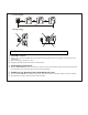
2. INSTALLATION OF CAMERA Dig Size: mm 100 95 113 2. 3. 4. 5. Attach the bracket to the wall, wherever you want to install the monitor. Secure the bracket with the supplied screws. Connect the cable connectors with 4 wires in polarity to the wafer on the rear of the monitor. Fasten the monitor onto the bracket Connect the spring wire of handset Plug the supplied 1A AC adapter to the DC IN jack on the rear of the monitor and plug it into AC 120V outlet. 140 1. 40 87 NO.2 NO.3 3 NO.
1. Attach the bracket to the wall, wherever you want to install the camera. Secure the bracket with the supplied screws (Refer to the above illustration). 2. Connect the cable connectors with 4 wires in polarity to the wafer on the rear of the camera. 3. Fasten the camera onto the bracket Note: • • Avoid places where the camera could be exposed to the direct sunlight or strong lighting sources for better pictures.
Correct wiring: 100M Wrong wiring: OPERATION 1. VISITOR CALLING ■ ■ ■ When a visitor presses the CALL button on the camera, the chime sounds and the visitor appears on the monitor screen automatically. Pick up the handset to speak to the visitor. Hanging up the handset returns the monitor to stand by mode. 2. MONITORING OPERATION ■ Press the MONITOR button when the handset is in position, you will see the camera’s field of view for about 90 seconds.
RVV 2 X 32/0.2 W/1.0mm cut area wire for electronic lock connection (reference distance﹤ 25m) 2 Electronic Lock AC120V AC120V TROUBLE SHOOTING If the product does not function properly, check the following points before contacting the service center. Problems No picture Picture flickering Normal sound, dim picture, picture too bright or too dark Picture smaller than screen No sound Picture not disappear SPECIFICATIONS MONITOR Cause and Remedies 1. AC Adapter not plugged in 2.
Display 4” flat CRT Resolution 380 TV lines Power source AC 120V/DC15V 1A Current consumption Operation: 750 mA, Stand-by: 10mA Conversation time Automatic off after 80 seconds Cable 4 wires in polarity Max. wiring distance 0.65mm 4 wire:50m, 5C2V coaxial cable: 80m Call signal sound Electronic chime: “ding dong” sound Operation temperature 0ºC to 40ºC Dimensions 210(W) x 215(D) x 70(H) mm Weight 2.6 Lbs CAMERA Image sensor 1/3” B/W C-Mos sensor Resolution 352(V) x 288(H) Minimum illumination 0.