INSTRUCTION MANUAL 30X DAY/NIGHT ZOOM CAMERA MODEL Z670 Copyright © 2009 Clover Electronics U.S.A.
1. IMPORTANT SAFETY PRECAUTIONS ▪ To prevent fire or shock hazard, do not expose the camera to rain or moisture. ▪ To avoid electrical shock, do not open the case of this product. ▪ Operate this product with the system such as COM22168, LCD2088, TFT2284C, ▪ ▪ ▪ ▪ ▪ TFT2288C and LCD261616 or by using only the power supply included. Do not overload electrical outlets or extension cords, this can result in fire or electric shock. Keep this product away from strong magnetic fields.
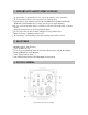
1. Video Output/DC power Input (6 pin Din) This is a 6pin Din connector for outputting video signals and for DC 12V input from the system such as COM22168, LCD2088, TFT2284C, TFT2288C and LCD261616. Note: When the 6pin Din is connected, do not apply 12V DC to the DC IN Jack ③ and connect the BNC video out ②. 2. Video Output (BNC) This is a BNC connector for outputting video signals. Note: When the BNC connector ② is used, do not connect the 6pin Din cable to the 6pin Din jack①. 3.
[Fig.4-1 Menu settings] ▪ LANGUAGE ▪ ▪ ▪ ▪ Choose “LANG (LANGUAGE)” in the Menu shown in Fig.4-1 by pressing “TELE”/”WIDE” button and select “EN (English)” by pressing “NEAR”/”FAR” button. FOCUS Choose “FOCUS” in the Menu shown in Fig.4-1 by pressing “TELE”/”WIDE” button and choose one among MANU (Manual), KCTL and AUTO by pressing “NEAR”/”FAR” button. ZOOM Choose “ZOOM” in the Menu shown in Fig.4-1 by pressing “TELE”/”WIDE” button and select “ON” or “OFF” by pressing “NEAR”/”FAR” button.
▪ WHITE BALANCE (WB) ▪ ▪ ▪ ▪ ▪ Choose “WB (WHITE BALANCE)” in the Menu shown in Fig.4-2 by pressing “TELE”/”WIDE” button and choose one among AUTO, OUT DOOR, INDOOR and LAMP by pressing “NEAR”/”FAR” button. IRIS Choose “IRIS” in the Menu shown in Fig.4-2 by pressing “TELE”/”WIDE” button and choose one among AUTO, FIX, NIGHT and MOVE by pressing “NEAR”/”FAR” button. AGC Choose “AGC” in the Menu shown in Fig.4-2 by pressing “TELE”/”WIDE” button and select “ON” or “OFF” by pressing “NEAR”/”FAR” button.
[Fig.4-4 Camera Menu] ▪ Click the “PAN/TILT (PELCO D)” button on the channel you wish to install the zoom camera and then the PAN/TILT Menu will be displayed as shown in Fig.4-5. [Fig.4-5 PAN/TILT Menu] ▪ Settings in the PAN/TILT Menu (Refer to System manual section 7-4.5 on page 90 for more detail) - Click the PTZ ID button in the PAN/TILT Menu shown in Fig.4-5, then the On Screen Keyboard will show up.
- Click the “PAN/TILT & REMOTE” button in the PAN/TILT menu shown in Fig.4-5, then the vendor lists will show up. Select “PELCO” on the vendor lists by clicking the mouse and then the protocol “PELCO D” will display. - Click the “BAUD RATE” button in the PAN/TILT menu and choose 2400bps among 1200bps, 2400bps, 4800bps, 9600bps, 19200bps, 38400bps, 57600bps and 115200bps on the Baud Rate pop-up window by clicking the mouse. - Do not change the settings for Data Bits, Stop Bits and Parity Bits.
[Fig.5-2Connecting bared copper wire] ▪ Connect the one end of 60’ 6pin Din cable to the Din jack on the rear of the zoom camera and the other end of cable to the DIN jack that the settings for PAN/TILT menu on the DVR system has been completed. -Be sure that the two arrows on the camera and the cable should be aimed at each other. -Do not apply DC 12V to the DC Jack and connect the BNC video out on the zoom camera when the 6 pin Din Cable is connected.
[Fig.6-1 PAN/TILT button] ▪ Click the Channel button in Fig. 6-2 and select the Channel number of zoom camera on the pop-up screen. PAN / TILT PRESET EXIT ZOOM / FOCUS CHANNEL [Fig.6-2 PAN/TILT CONTROL window] ▪ Click and hold the “+” or “-“ button for Zoom In/Out until getting the best quality of objects. If the Focus is set to “AUTO” on the zoom camera, it won’t be adjusted by the “+” or “-“button. The function of PAN/TILT and PRESET are not available on the Zoom Camera. 7.
8. SPECIFICATIONS Image pickup device TV system Resolution Minimum illumination Video output S/N ratio Gamma characteristics Electronic Shutter Speed Zoom White Balance Gain Control Control Interface Baud Rate Focus Adjustment Current consumption Power supply Operational temperature Dimensions Weight SONY Color CCD NTSC 480 TV lines 0.5 Lux 1.0v p-p composite @75 ohms More than 48db 0.45 1/60 to 1/100,000sec Up to 30X Max.
HS13HB MBK010 ADT241200 Outdoor camera housing w/heater and blower Mounting bracket for HS13HB AC 24V 1.2A AC power supply for HS13HB 11. LIMITED 1 YEAR WARRANTY This warranty gives the original purchaser specific legal rights and you may also have other rights, which may vary from state to state. If our products do not function because of any defect in material or workmanship, we will repair it for free for 1 year on parts and labor from the date of original purchase.