TH82 Series Reference Manual TH82 THERMAL PRINTER REFERENCE MANUAL Version 1.0 MAR.2004 CLOVER Electronics Co., Ltd.
CONTENTS TH82 Series Reference Manual INTRODUCTION ...............................................................................................................................3 FCC CLASS B ............................................................................................................................................................. 3 DECLARATION OF CONFORMITY .........................................................................................................................
TH82 Series Reference Manual INTRODUCTION FCC CLASS B This equipment generates and uses radio frequency energy and if not installed and used properly, that is, in strict accordance with the manufacturer's instructions, may cause interference to radio and television reception.
TH82 Series Reference Manual ABOUT THIS MANUAL GETTING STARTED CHAPTER 1 contains information on unpacking the printer and setting it up. CHAPTER 2 contains information on using the printer. CHAPTER 3 contains information of maintenance and troubleshooting. CHAPTER 4 contains security information. SPECIFICATION CHAPTER 5 contains printers’ specification. CHAPTER 6 contains character code tables and commands. APPENDIX A contains information on setting and changing the DIP switches.
TH82 Series Reference Manual 1 CHAPTER 1 SET UP 1.1 UNPACKING Check for the following items in your box. 1 2 3 4 thermal printer roll paper AC adapter AC cord 1.2 PRINTER COMPONENTS PRINTER COVER COVER OPEN KNOB CONTROL PANEL PAPER CUTTER COVER POWER SWITCH Before connecting any of the cables, please turn off the HOST device. 1.3 ATTACHING INTERFACE CABLE TO THE PRINTER You need an appropriate interface cable. Refer to section 5.3.1 on page 13 for cable details.
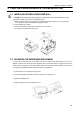
TH82 Series Reference Manual 1.4 ATTACHING THE DRAWER, GROUND WIRE AND POWER SUPPLY DRAWER KICK CABLE DC CABLE 1.4.1 GROUND WIRE THE DRAWER CAUTION : You need a drawer that fits the printer’s specification. Do not connect a telephone line to the drawer kick-out connector. Plug the drawer kick cable into the kick-out connector. If two drawers are used, use a Y-cable that meets the specifications on page 14 to ensure that both drawers receive signals correctly. 1.4.
TH82 Series Reference Manual 2 CHAPTER 2 OPERATION Use the indicator’s lights to monitor the printing status. 2.1 POWER SWITCH Turn the printer ON or OFF. 2.2 CONTROL PANEL 2.2.1 FEED Press the FEED button to advance the paper by one line. Hold down the FEED button to advance paper continuously. 2.2.2 ONLINE Press the ONLINE button to put the printer online or offline. The green light indicates the printer is online.
TH82 Series Reference Manual 3 CHAPTER 3 MAINTERNANCE & TROUBLESHOOTING 3.1 INSTALLING OR REPLACING PAPER ROLL CAUTION : make sure that paper rolls meets printer’s specification. Do not use paper rolls that have one end glued to the core. This causes excessive load on the paper feed. 1 : Make sure that the printer is not printing or receiving data, and open the printer cover by pressing the cover open knob. Unroll several inches of the paper as shown. 2 : Insert the paper roll as shown.
TH82 Series Reference Manual 3.3 PAPER JAM CAUTION : Do not touch the printer head because they are very hot after continuous printing. Do not attempt to clear a paper jam until the printer cools down. 1 : Turn the printer off and press the cover open button. 2 : Remove the jammed paper and replace the paper roll. If the printer cover can’t be opened after a paper jam, check the Automatic Paper Cutter. 1 : Remove the Automatic Paper Cutter Cover.
TH82 Series Reference Manual Error Contents Check/points to check ERROR Indicator is ON The Printer Cover doesn’t close completely Can’t print the self test ONLINE Indicator is not ON Printing causes the paper to feed Solutions Open the Cover by pressing the Cover Open Button, and Close it again by pushing at center of ERROR Indicator doesn’t light up ON LINE Indicator lights up after pushing Something is wrong with Paper Sensor on the when out of paper.
TH82 Series Reference Manual 4 CHAPTER 4 IMPORTANT SAFETY INFORMATION ■ ■ ■ ■ ■ ■ ■ ■ ■ ■ ■ ■ ■ Read all the direction and keep this manual for future use. Follow all of the warnings and instructions marked on the product and in this manual. Unplug this product from the wall outlet before cleaning. Do not use liquid or aerosol cleaners. Do not use this product near water. Do not place this product on an unstable cart, stand or table.
TH82 Series Reference Manual 5 CHAPTER 5 SPECIFICATION 5.1 PRINTING SPECIFICATION TYPE TH-82 TH-200, TH-200s Model NO. of Printer Mechanism LTPE347B-C576 ※1 LTPF347A-C576 ※1 Printing Method Direct Line Thermal Direct Line Thermal Dot pitch 8 dot/mm 8 dot/mm Printing Speed 75 mm per second (Max.) 210 mm per second (Max.
TH82 Series Reference Manual 5.2 PAPER SPECIFICATION Paper Width: Paper roll size: Specified paper: Paper roll spool diameter: 79.5±0.5mm(3.13±0.02”) Roll diameter: Maximum 80mm (3.15”) Take-up paper roll width: 80 +0.5/-1.0mm (3.15+0.02/-0.04”) Specified thermal roll paper: NTP080-80 [Original paper: TF50KS-E2C Nippon Paper Industries Co., Ltd.] Packaged roll paper: [Original paper: PD160R-N (Oji Paper Mfg. Co., Ltd.)] In Japan: Nakagawa Manufacturing Co., Ltd. In U.S.A: Nakagawa Mfg. (U.S.A.) Inc.
TH82 Series Reference Manual 5.3.3 POWER SUPPLY CONNECTOR The connector is connected the printer to an external power source. PIN SIGNAL 1 +24V 2 GND 3 NC SHELL F.G 2 3 1 SHELL CONNECTOR MODEL: Printer side: Hosiden TCS7960-532010 or equivalent User side: Hosiden TCP8927-631100 or equivalent Hosiden TCP8927-531100 or equivalent 5.3.4 DRAWER KICK-OUT CONNECTOR The pulse specified by ESC p or DLE DC4 is output to this connector.
TH82 Series Reference Manual 5.4 PACKAGE SPECIFICATION OUTER CASE Weight: 10.5 Kg 330 mm 560 mm 410 mm Serial no. Care mark on both sides Model name *Mark “C” should be stamped below the model name for identification. ENCLOSED GOODS: DISPLAY INNER CASE: 4pcs CARE MARK, MODEL NAME: stamped in 2 parts (both sides) SERIAL NO stickers attached: 4pcs SEALING TAPE: OPP, clear color, “H” shaped taping INNER CASE Weight: 2.4kg 305 mm 265 mm 200 mm Model name Serial No.
TH82 Series Reference Manual 6 CHAPTER 6 COMMANDS 6.
TH82 Series Reference Manual COMMAND NAME ESC ∼ FS g1 Transmit drawer status Turn upside-down printing mode on/off Specify print density Write to NV user memory FS g2 FS p FS q Read to NV user memory Print NV bit image Define NV bit image ESC u ESC { FS r FS ! Read NV bit image Specify Kanji character print mode FS & Specify Kanji character mode FS FS .
TH82 Series Reference Manual 6.2 DESCRIPTION OF THE COMMANDS The name of the command. The code sequence. ASCII indicates ASCII equivalents. HEX indicates the hexadecimal equivalents. < >H represents hexadecimal number, < > represents decimal number and [ ]k represents a repeat count of k-times. [RANGE] Describes an argument value for the command. [FUNCTION] Describes the function of the command. [CAUTION] Describes a caution as required. [DEFAULT] Describes an initial value for the command as required.
TH82 Series Reference Manual DLE NUL Clear [FORMAT] <10>H<00>H [FUNCTION] *DLE NUL clears the data in the print buffer. *This command clears part of the printer configuration. DLE ENQ Real-time request to printer [FORMAT] <10>H<05>H [RANGE] 1≦n≦2H [FUNCTION] DLE ENQ responds to a request in real time from the HOST, specified by n. n=1:After removing a cause of the error, the printing restarts from the beginning of the line where the error occurred.
TH82 Series Reference Manual DLE DC4 Real-time pulse output [FORMAT] <10>H<14>H [RANGE] n=1 m=0,1 1≦t≦8H [FUNCTION] This command outputs the pulse specified by t to connector pin m as follows. m Connector pin 0 Plug 1 1 Plug 2 The pulse ON time is t x100msec. and the OFF time is t x100msec.. [DETAILES] *This command is ignored when the printer is in an error status while this command is processed. *When ESC p or DEL DC4 is executed, this command is ignored and no pulse is sent.
TH82 Series Reference Manual 2 3 4 5 6 7 Drawer open/close signal(connector pin 3) Off/On Not used Undefined Undefined Not used Low Online - High Offline Fixed to off Fixed to off - n = 2: Offline status VALUE 0 1 0 Not used Fixed to off 1 Not used Fixed to off 2 Printer cover Cover is closed Cover is open 3 Paper FEED button Not feeding Under feeding 4 Not used Fixed to off 5 Paper-end stop No stop stop 6 Error No error Error 7 Not used Fixed to off Bit 5: Printing stops when the paper end sensor d
TH82 Series Reference Manual ESC FF Print data in page mode [FORMAT] <1B>H<0C>H [FUNCTION] Prints all buffered data in the printing area collectively in page mode. [DETAILES] *This command is enabled only in page mode. *After printing, the printer keeps the buffered data, setting values for ESC T and ESC W, and the position for buffering character data.
TH82 Series Reference Manual [CAUTION] Sets the distance from the beginning of the line to the position at which subsequent characters should be printed. The distance from the beginning of the line to the print position is (nl + n2x256) x (vertical or horizontal motion unit). Setting outside the printable area are ignored.
TH82 Series Reference Manual 0≦n2≦1 High 8 bits of the number of printing dot. Bit image data 0≦d≦FFH [FUNCTION] Prints data following the bit image modes specified by m m Mode 0 1 32 33 8-dot single-density Vertical direction Vertical direction Horizontal direction No. of dots Dot density Dot density 8 8 24 24 67DPI 67DPI 200DPI 200DPI 100DPI 200DPI 100DPI 200DPI 8-dot double-density 24-dot single-density 24-dot double-density No.
TH82 Series Reference Manual n 0,48 1,49 2,50 [CAUTION] Function Turns off underline mode Turns on underline mode of 1-dot thick Turns on underline mode of 2-dot thick *An underline is attached to the full character width including right side character spacing, but not attached to the space set by HT and 90o clockwise rotated character by ESC V.
TH82 Series Reference Manual *n1 is the total block number of logo pattern which should be set. [CAUTION] Block number 1(n2) Total bock number(n1) Block number N-1 Block number N ・n2is the block number which should be set. ・data1 – data720 sets logo pattern data.
TH82 Series Reference Manual [CAUTION] *The DIP switch settings are not checked again. *The data in the receive buffer is not cleared. *The macro definition is not cleared. *The NV bit image data is not cleared. ESC D Set horizontal tab positions [FORMAT] <1B>H<44>H[d1...dk]<00> [RANGE] 0≦d≦FFH 1≦k≦32 [FUNCTION] Sets horizontal tab positions. [CAUTION] *d specifies the column number.
TH82 Series Reference Manual n=<*******0>B n=<*******1>B Double-strike mode is turned off. Double-strike mode is turned on. [DETAILES] *n is valid only for the lowest bit. *Printer output is all the same with emphasized mode. [DEFAULT] n=0 (double-strike mode off) ESC J Print and feed paper [FORMAT] <1B>H<4A>H [RANGE] 0≦n≦255 [FUNCTION] Prints the data in the print buffer and feeds the paper [n x vertical or horizontal motion unit].
TH82 Series Reference Manual [DETAILES] ESC R 1,49 Font B (8x16) selected. The ESC ! command can also select the character fonts but the setting of the last received command is effective. Select an international character set [FORMAT] <1B>H<52>H [RANGE] 0≦n≦13 [FUNCTION] *Selects an international character set. *The code table is as follows.
TH82 Series Reference Manual ESC T Select print direction in page mode [FORMAT] <1B>H<54>H [RANGE] 0≦n≦3 、48≦n≦51 [FUNCTION] Selects the print direction and start position in page mode.
TH82 Series Reference Manual ESC W Set printing area in page mode [FORMAT] <1B>H<57>H [RANGE] 0≦xL、xH、yL、yH、dxL、dxH、dyL、dyH≦255 ATTN: Except dxL=dxH=0 or dyL=dyH=0 [FUNCTION] Sets printing area and position.
TH82 Series Reference Manual ESC ╲ Select relative print position [FORMAT] <1B>H<5C>H [RANGE] 0≦n1≦FFH 0≦n2≦FFH [FUNCTION] *Sets the print starting position based on the current position. *[(n1+n2×256)× horizontal or vertical motion unit]. [CAUTION] *Setting that exceeds the printable area is ignored. *When the printable area moves from current position to the right, specify positive direction and to the left, specify negative direction.
TH82 Series Reference Manual ESC c 3 Select paper sensor to output paper end signals [FORMAT] <1B>H<63>H<33>H [RANGE] 0≦n≦255 [FUNCTION] Selects the paper sensor to output paper end signals. BIT FUNCTION HEX. 0 This command is invalid. Paper roll near end sensor disabled 00 Paper roll near end sensor enabled. 01 Paper roll near end sensor disabled 00 Paper roll near end sensor enabled. 02 Paper roll end sensor disabled 00 Paper roll end sensor enabled.
TH82 Series Reference Manual ESC c 4 Select paper sensor to stop printing (Near-end sensor model only) [FORMAT] <1B>H<63>H<34>H [RANGE] 0≦n≦255 [FUNCTION] Selects the paper sensor to stop printing when a paper near end is detected. VALUE BIT FUNCTION 0 1 0 Paper roll near end sensor. Disabled. Enabled. 1 Undefined. 2 Undefined. 3 Undefined. 4 Undefined. 5 Undefined. 6 Undefined. Undefined. 7 *This function is valid only on near-end sensor model .
TH82 Series Reference Manual ESC k Select characters (ANK) [FORMAT] <1B>H<6B>H [RANGE] 0≦n≦1 [FUNCTION] [CAUTION] Select ANK characters specified by n. VALUE FUNCTION 0 1 Select characters Mintyo Gothic Undefined Undefined Undefined Undefined Undefined Undefined Undefined This command ignores in the model with one of above characters ESC m Partial cut (one point left cut) [FORMAT] <1B>H<69>H [RANGE] - [FUNCTION] Sets Partial cut.
TH82 Series Reference Manual ESC p Generate pulse [FORMAT] <1B>H<70>H [RANGE] m=0,1,48,49 0≦n1≦FFH 0≦n2≦FFH n1≦n2 [FUNCTION] m=0,48: Outputs the pulse specified by n1 and n2 to drawer no. 1. m=1,49: Outputs the pulse specified by n1 and n2 to drawer no. 2. [CAUTION] *The pulse ON time is n1 x 2 msec. and OFF time is n2 x 2 msec. *If n2
TH82 Series Reference Manual 37/37
TH82 Series Reference Manual ESC u Transmit drawer status [FORMAT] <1B>H<75>H [RANGE] n=0、48 [FUNCTION] Transmits the status of drawer sensor. Status bit 0 = 0: plug 1 Closed Bit 0 = 1: plug 1 Open Bit 1 = 0: plug 2 Closed Bit 1 = 1: plug 2 Open ESC { Turn upside-down printing mode on/off [FORMAT] <1B>H<7B>H [RANGE] 0≦n≦FFH [FUNCTION] Turns upside-down printing mode on or off. *n = Turn off even number *n = Turn on odd number.
TH82 Series Reference Manual ESC ∼ Select print density [FORMAT] <1B>H<7E>H [RANGE] m=0, 0≦n≦7 [FUNCTION] Selects print density. Sets print density specified by n as follows. n=0 Lightest n=7 Deepest [CAUTION] This command is enabled only when processed at the beginning of a line. [DEFAULT] n=3 FS g 1 Write to NV user memory [FORMAT] <1C>H<67>H<31>H[d1...dk] [RANGE] m=0 [FUNCTION] Writes data to NV(Non-volatile) user memory. *m is set to 0.
TH82 Series Reference Manual FS g 2 Read to NV user memory [FORMAT] <1C>H<67>H<32>H [RANGE] m=0 0≦(a1+(a2x256)+(a3x65536)+(a4x16777216))≦1023 1≦(nL+(nHx256))≦80 [FUNCTION] *Transmits data of NV (Non-volatile) user memory. *m is set to 0. *a1、a2、a3 and a4 specify the stored starting address of the data to (a1+(a2x256)+(a3x65536) + (a4x16777216). *nL、nH set the number of stored data to (nL+(nHx256)) bytes.
TH82 Series Reference Manual FS p Print NV bit image [FORMAT] <1C>H<70>H [RANGE] 0≦n≦255 0≦m≦3、48≦m≦51 [FUNCTION] Prints a NV (Non-volatile) bit image n using the mode specified by m. m Mode Vertical Dot Density 0,48 Normal 200 dpi 1,49 Double width 200 dpi 2,50 Double height 100 dpi 3,51 Quadruple 100 dpi [dpi : Dots per 25.4mm (dots per inch)] Horizontal Dot Density 200 dpi 100 dpi 200 dpi 100 dpi *n specifies the number of the NV bit image. *m specifies the bit image mode.
TH82 Series Reference Manual FS q Define NV bit image [FORMAT] <1C>H<71>H[xL xH yL yH d1...dk]1...[xL xH yL yH d1...dk]n [RANGE] 1≦n≦255 0≦xL≦255 0≦xH≦3 (When 1≦(xL+xH x256)≦1023) 0≦yL≦255 0≦yH≦1 (When 1≦(yL+yH x256)≦288) 0≦d≦255 k=(xL+xH x256)x(yL+yH x256)x8 Total defined data area = 2M bits (256K bytes) [FUNCTION] Defines the NV (Non-volatile) bit image specified. *n specifies the number of the defined NV bit image.
TH82 Series Reference Manual [CAUTION] *Frequent command execution may cause damage the NV memory. Thus, it is strongly recommended to write the NV memory 10 times a day. *The printer executes a hardware reset after finished writing to the NV memory. Thus, download characters, download bit images and macros should be undefined, the printer clears the receive buffer and initializes the mode to the mode that was effective at power on. At this time, DIP switch setting are read again.
TH82 Series Reference Manual FS r Read NV bit image This command is invalid. FS ! Specify Kanji character print mode [FORMAT] <1C>H<21>H [RANGE] 0≦n≦255 [FUNCTION] Specifies print mode for Kanji characters.
TH82 Series Reference Manual FS & Specify Kanji character mode [FORMAT] <1C>H<26>H [RANGE] - [FUNCTION] Specifies Kanji character mode. [CAUTION] [For Japanese model] *When the Kanji character mode is selected, the printer processes all the following data as two bytes code. *Kanji codes are processed in the order of the first byte and second byte. *Kanji character is off by default.
TH82 Series Reference Manual FS - Turn underline mode on/off for Kanji character [FORMAT] <1C>H<2D>H [RANGE] 0≦n≦2, 48≦n≦50 [FUNCTION] Turns underline mode on or off for Kanji characters. n Function 0,48 Turns off underline mode for Kanji characters. 1,49 Turns on underline mode for Kanji characters with 1 dot thick 2,50 Turns on underline mode for Kanji characters with 2 dot thick.
TH82 Series Reference Manual FS 2 Define download Kanji character [FORMAT] <1C>H<32>Hdata1……data72 <1C>H<32>Hdata1……data32 [RANGE] Japanese Kanji (JIS) Japanese Kanji (SHIFT-JIS) Chinese Kanji (GB2312) Korea Kanji (KS C 5601) 24 X 24 dots 16 X 16 dots a1=77H, 21H≦a2≦7EH a1=ECH, 40H≦a2≦7EH / 80H≦a2≦9EH a1=FEH, A1H≦a2≦FEH a1=FEH, A1H≦a2≦FEH [FUNCTION] Defines user-defined Kanji characters for the character code specified by a1, a2.
TH82 Series Reference Manual FS C Select Kanji character code system (Japanese model only) [FORMAT] <1C>H<43>H [RANGE] n=0,1,48,49 [FUNCTION] Selects a Kanji character code system. n 0,48 1,49 Selection JIS code system SHIFT JIS system [DETAILES] *In the JIS code system, the available codes are as follows and this command is valid only on Japanese model. The first byte: <21>H∼<7E>H The second byte : <21>H∼<7E>H *In the SHIFT JIS code system, the available codes are as follows.
TH82 Series Reference Manual FS W Turn quadruple-size mode on/off for Kanji character [FORMAT] <1C>H<57>H [RANGE] 0≦n≦255 [FUNCTION] *Turns quadruple-size mode on or off for Kanji characters specified by n.
TH82 Series Reference Manual GS ! Select character size [FORMAT] <1D>H<21>H [RANGE] 0≦n≦FFH [FUNCTION] Selects the character size, height and width. Bit 0 1 2 3 4 5 6 7 Function Character height selection See table 2 Character width selection See table 1 Table 1 Character width selection Hex. Width 00H 1(normal) 10H 2(double-width) 20H 3 times 30H 4 times 40H 5 times 50H 6 times 60H 7 times 70H 8 times [DETAILES] Value Table 2 Character height selection Hex.
TH82 Series Reference Manual GS $ Set absolute vertical print position in page mode [FORMAT] <1D>H<24>H [RANGE] 0≦nL≦255、1≦nH≦255 [FUNCTION] Sets the absolute vertical print position which is based on the starting position in page mode. The absolute print position is set to [(nL + nH x 256) x (horizontal or vertical motion unit)]. [CAUTION] *This command is valid only in page mode. *This command is ignored when the setting of the absolute print position exceeds the specified printing area.
TH82 Series Reference Manual GS ( A Execute test printing [FORMAT] <1D>H<28>H<41>H [RANGE] (pL+(pH x256)=2 (pL=2、pH=0) 0≦n≦2、48≦n≦50 This command is invalid. 1≦m≦3、49≦m≦51 [FUNCTION] Executes a test print specified. *pL, pH specifies the number of the parameter as (pL+(pH x256) bytes. *n specifies the paper to be tested as follows. n Paper 0,48 Basic sheet (paper roll) 1,49 Paper roll 2,50 *m specifies a test pattern as follows.
TH82 Series Reference Manual GS : Start/end macro definition [FORMAT] <1D>H<3A>H [RANGE] - [FUNCTION] Starts or ends macro definition. [CAUTION] *Macro definition is useful when the same contents need to be printed several times. *Macro definition starts when this command is received during normal operation. Macro definition ends when this command is received during macro definition. *When GS ^ is received during macro definition, the printer stops macro definition and clears the definition.
TH82 Series Reference Manual GS H Select printing position of HRI characters [FORMAT] <1D>H<48>H [RANGE] 0≦n≦3, 48≦n≦51 [FUNCTION] *Selects the printing position of HRI characters when printing a bar code. *n = 0,48: Not printed. *n = 1,49: Above the bar code. *n = 2,50: Below the bar code. *n = 3,51: Above and below the bar code.
TH82 Series Reference Manual GS L Sets left margin [FORMAT] <1D>H<4C>H [RANGE] 0≦nL≦255 0≦nH≦255 [FUNCTION] *Sets the left margin specified by nL and nH. *The left margin is set to [(nL + nH x 256) x horizontal motion unit]. Printable area Left margin Printing area width [RANGE] *This command is effective only when processed at the beginning of a line in standard mode. *If this command is processed in page mode, the printer executes only internal flag operation.
TH82 Series Reference Manual GS P Specify basic calculate pitch [FORMAT] <1D>H<50>H [RANGE] 0≦x≦255 0≦y≦255 [FUNCTION] *Specifies the horizontal and vertical motion units to approximately 25.4/xmm{(1/x) inches} and approximately 25.4/ymm{(1/y) inches}. *When x = 0, the default setting of horizontal motion unit is used. *When y = 0, the default setting of vertical motion unit is used.
TH82 Series Reference Manual GS W Set printing area width [FORMAT] <1D>H<57>H [RANGE] 0≦nL≦255 0≦nH≦255 [FUNCTION] *Sets the printing area width specified by nL, nH. *The printing area width is [(nL + nH x 256) x horizontal motion unit]. Printable area Left margin [FUNCTION] Printable area width *This command is effective only when processed at the beginning of a line in standard mode. *This command executes only internal flag operations in page mode.
TH82 Series Reference Manual *If the width set for the printing area is less than one line in horizontal, the following is processed only on the line in question when bit image is developed. ① The printing area width is extended to the right to accommodate one line in horizontal for the bit image within the printable area. ② If the printing area width cannot be extended sufficiently by executing ①, the left margin is reduced to accommodate on line in horizontal.
TH82 Series Reference Manual GS ^ Execute macro [FORMAT] <1D>H<5E>H 0≦n1≦255 [RANGE] 0≦n2≦255 0≦n3≦1 [FUNCTION] n3 0 1 [CAUTION] *Executes a macro. *n1 specifies the number of times to execute the macro. *n2 specifies the waiting time when the macro is executed. *n3 specifies macro executing mode. Function The macro executes n1 times continuously at the interval specified by n2.
TH82 Series Reference Manual GS a Enable/disable Automatic Status Back [FORMAT] <1D>H<61>H [RANGE] 0≦n≦255 [FUNCTION] *Enable or disable Automatic Status Back (ASB) and select the status.
TH82 Series Reference Manual b: Second byte (error information) Bit 0 1 2 3 4 5 6 7 Value Status Undefined Undefined Mechanical error Undefined Not used Unrecoverable error Head temperature error Not used 0 1 - Not occurred occurred Fixed to 0 Not occurred occurred Not occurred occurred Fixed to 0 c: Third byte (paper sensor information) Value 0 1 0 Paper roll near-end sensor Paper enough Paper near end 1 Paper roll near-end sensor Paper enough Paper near end 2 Paper roll end sensor Paper present Pa
TH82 Series Reference Manual GS b Turn smoothing mode on/off [FORMAT] <1D>H<62>H [RANGE] 0≦n≦255 [FUNCTION] Turns smoothing mode on or off. When n = <*******0>B, smoothing mode is turned off. When n = <*******1>B, smoothing mode is turned on. [DETAILES] *Only the lowest bit of n is effective. *Smoothing mode is available for built-in, download characters. *Even if smoothing mode is turned on, smoothing is not processed when each of character width or character height is the normal size.
TH82 Series Reference Manual GS k Print bar code [FORMAT] ①<1D>H<6B>H...<00>H ②<1D>H<6B>H... [RANGE] ①0≦m≦6 ②65≦m≦72 [FUNCTION] Selects a bar code system and prints the bar code. ① m 0 1 2 3 4 5 6 Bar code system Number of characters(k) UPC-A 11≦k≦12 UPC-E 11≦k≦12 JAN13(EAN13) 12≦k≦13 JAN8(EAN8) 7≦k≦8 Code39 1≦k Interleaved 2 of 5(ITF) 1≦k Codabar 1≦k *This command ends with NUL code.
TH82 Series Reference Manual GS r Transmit status [FORMAT] <1D>H<72>H [RANGE] 1≦n≦2, 49≦n≦50 [FUNCTION] *Transmits the status specified by n. n Function 1,49 Transmits paper sensor status 2,50 Transmits drawer open sensor status *The status which should be transmitted as follows.
TH82 Series Reference Manual GS v 0 Print raster bit image [FORMAT] <1D>H<76>H<30>H[d1...dk] [RANGE] 0≦m≦3、48≦m≦51 0≦xL≦255 0≦xH≦255 0≦yL≦255 0≦yH≦8 0≦d≦255 k=(xL + xH x 256) x (yL + yH x 256) [FUNCTION] (k ≠ 0) Prints raster bit image specified by mode m.
TH82 Series Reference Manual GS w Select bar code width [FORMAT] <1D>H<77>H [RANGE] 2≦n≦4 [FUNCTION] Sets the horizontal size of the bar code to dot n. [DEFAULT] n=3 This command is invalid.
TH82 Series Reference Manual APPENDIX A DIP SWITCH SETTING & CHECKING THE DIP SWITCHES No.
TH82 Series Reference Manual APPENDIX B FIRMWARE DOWNLOAD The following steps can help you to download programs for both TH-80 series. Download TH82 Series Program 1: FILE Confirm that you have the following files. Copy2Com.exe Program for the download TH80xxxx.hex Program file. xxxx depends on the version NO. Ex: “TH82EPS108.hex” readme.txt contains this text, APPENDIX B. Check the “readme.txt” for last minute changes. 2: DIPSW setting Turn the printer off, set dip switch 2 on, then turn the printer on.